
Coater

A coating device and coating technology, which are applied to the device, coating, optics and other directions of coating liquid on the surface, can solve the problems of lens dripping and coating liquid accumulation.

Active Publication Date: 2009-01-28
TOKUYAMA CORP
View PDF2 Cites 14 Cited by
  • Summary
  • Abstract
  • Description
  • Claims
  • Application Information

AI Technical Summary

Problems solved by technology

In addition, when the highly viscous photochromic coating liquid is spin-coated on the lens, there is a problem that even if the centrifugal force during rotation is generated, the coating liquid will accumulate on the peripheral portion of the lens and flow toward the side surface of the lens. dripping

Method used


Image

  • Coater
  • Coater
  • Coater

Examples


Embodiment Construction

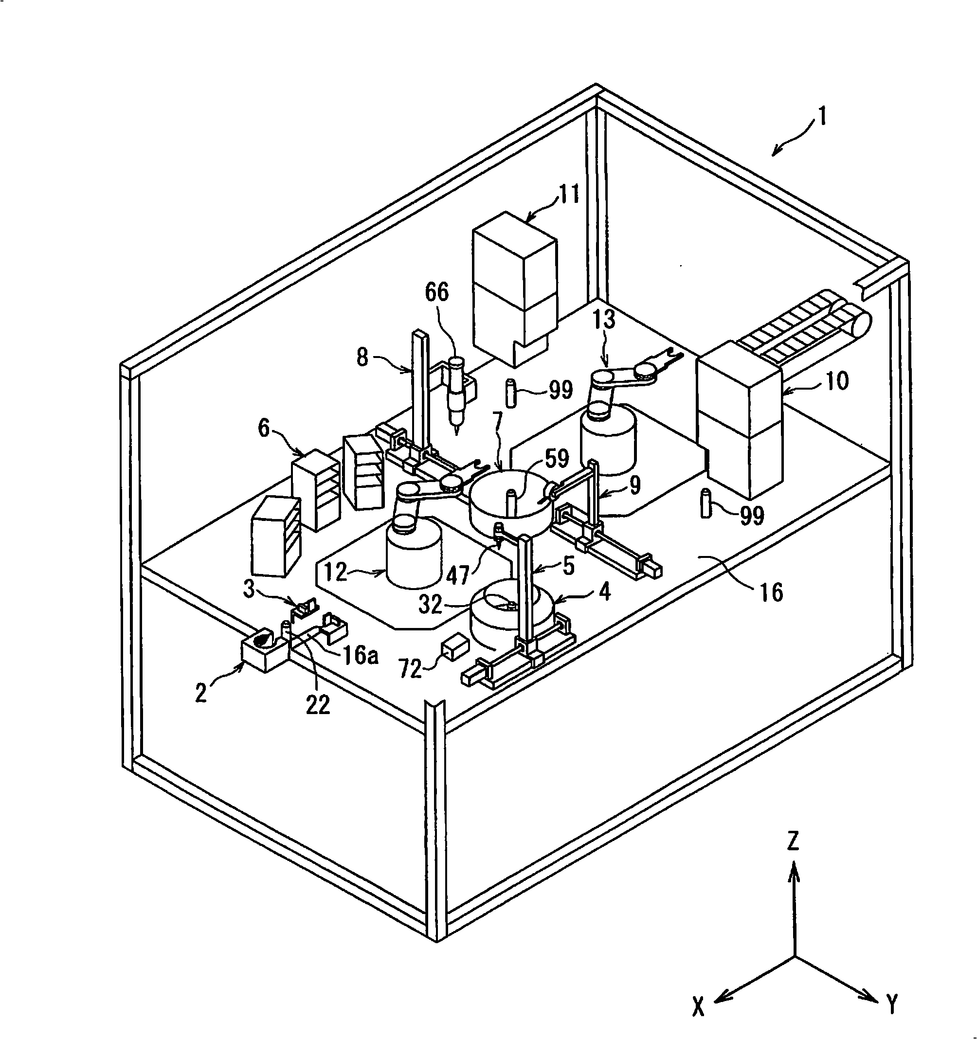
[0039] Next, a coating apparatus according to an embodiment of the present invention will be described with reference to the drawings.

[0040] In this manual, the figure 1 The direction of the X-axis direction of the coating device is referred to as the coating device width direction, the direction of the Y-axis direction is referred to as the front-rear direction, and the direction of the Z-axis direction is referred to as the vertical direction.

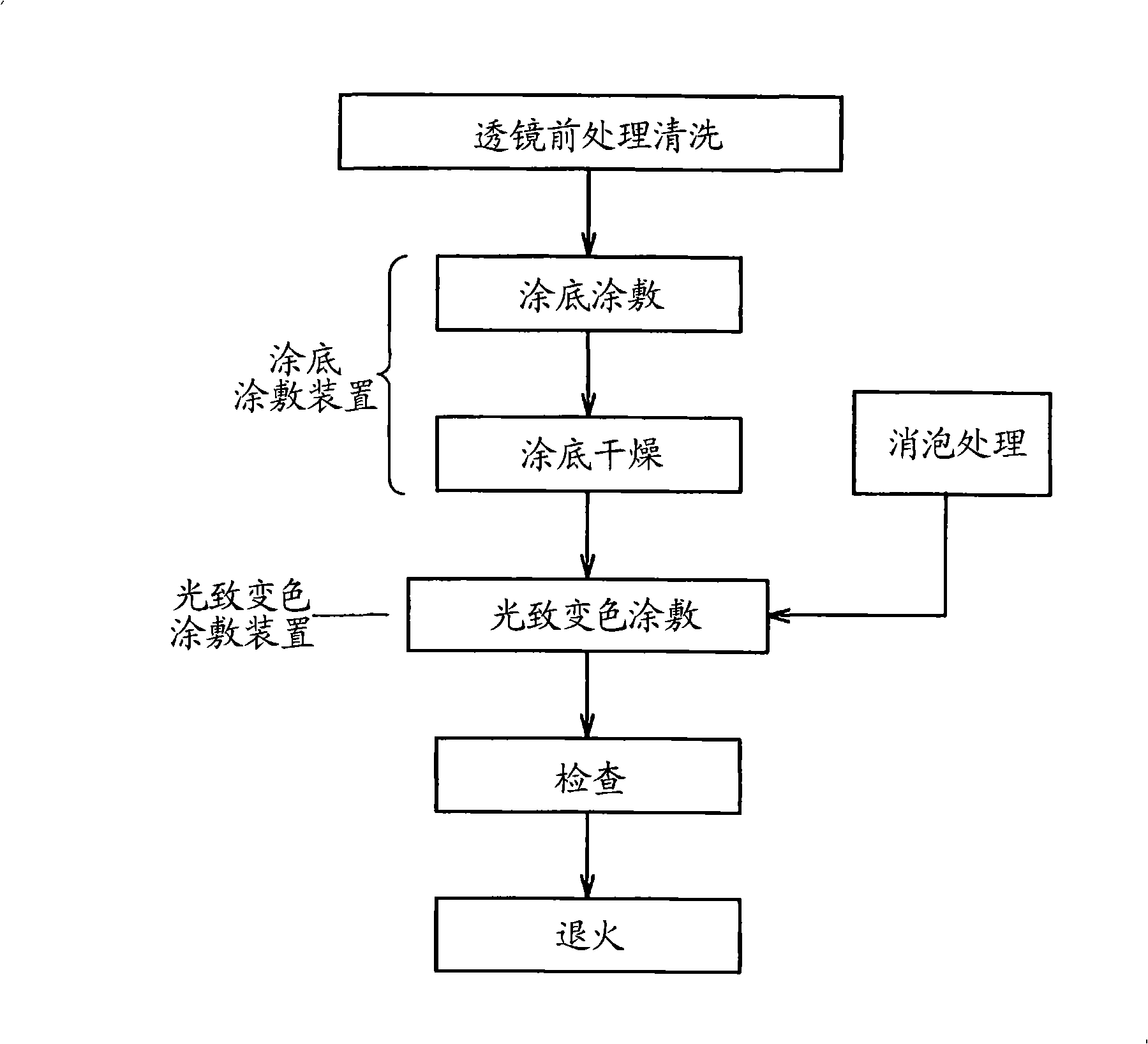
[0041] like figure 1 The illustrated coating apparatus 1 is an apparatus for forming a coating film on a lens. The coating treatment is from such as figure 2 In the photochromic coating operation steps from the lens pretreatment cleaning to annealing shown in the flow chart, primer coating treatment (hereinafter also referred to as primer coating) and photochromic coating treatment (hereinafter also referred to as photochromic coating) are carried out. color-changing coating).

[0042] The coating device 1 mainly includes a c...


PUM


Abstract

A coater for forming a stable photochromic coating film. In the path of one handling device, the lens support shafts of a lens height measuring sensor, a primer-side lens support, and a lens drying box are provided; and in the path of the other handling device, and the lens support shafts of a UV device are provided. The lens support shafts of the primer-side lens support are provided in the paths of both handling devices. In a coater, a centering device, a lens height measuring device, a primer liquid coating device, a primer spin device, a drying device, a photochromic liquid coating device, a photochromic spin device, a UV device, and lens transfer means having a pair of handling devices are provided. In this coater, the lens support sections of the centering device, the lens height measuring device, the primer spin device, and the drying device are arranged in the path of one of the handling devices of the lens transfer means, the lens support section of the UV device is disposed in the other handling device of the lens transfer means, and the lens support sections of the photochromic spin device are arranged in the paths of both handling devices of the lens transfer means. Therefore, many photochromic lens can be efficiently fabricated.

Description

technical field [0001] The present invention relates to a coating apparatus capable of performing, for example, photochromic coating with high quality on lenses such as eyeglasses. Background technique [0002] Among the materials that change color due to light are photochromic substances. A photochromic substance has the property of reversibly changing its structure depending on the presence or absence of ultraviolet rays, thereby changing the absorption spectrum. This is a property of a single chemical substance that reversibly generates isomers with different absorption spectra due to the action of light when one isomer is irradiated with light of a specific wavelength. The other isomer produced returns to the color of the original isomer due to heat or light of another wavelength. [0003] There are photochromic glasses which utilize the properties of the photochromic material to the lens. Photochromic glasses have such a function that the lenses are rapidly colored t...

Claims


Application Information

Patent Timeline
IPC IPC(8): G02B1/10B05C9/12B05C11/00B05C11/08B05C11/10G02C7/10G02C13/00
Inventor 高桥直人河野敦之山本修平
Owner TOKUYAMA CORP
Learn More