
Abnormality monitoring device in elevator car

An elevator car and abnormal monitoring technology, applied in transportation, packaging, elevators, etc., can solve problems such as time-consuming and labor-intensive, and can not be installed correctly, so as to achieve the effect of preventing malfunction and high reliability

Active Publication Date: 2009-02-04
HITACHI BUILDING SYST CO LTD
View PDF0 Cites 28 Cited by
  • Summary
  • Abstract
  • Description
  • Claims
  • Application Information

AI Technical Summary

Problems solved by technology

[0004] In the prior art described above, the elevator car is illuminated with the door closed and there are no passengers in the car as the basic image, and the basic image is compared with the image of the floor of the car taken by a camera to determine To detect the presence or absence of passengers, but when window glass is installed on the door of the elevator, the morning sun or sunset may shine through the window glass, or sunlight may enter the car due to changes in the angle of sunlight in summer and winter, etc., so when comparing In the case of the basic image and the image captured by the camera, there is a possibility that a passenger is falsely detected even though there is no passenger in the car
[0005] In addition, the initial setting work of setting the image captured by the camera to be compared with the basic image is time-consuming and labor-intensive because the personal computer or monitor device is connected to the image output terminal of the camera, and the setting is performed while viewing the displayed image. The problem
[0006] In addition, when the elevator user changes the shooting direction of the camera or sprays the camera, etc., there is a problem that the device cannot work correctly.

Method used


Image

  • Abnormality monitoring device in elevator car
  • Abnormality monitoring device in elevator car
  • Abnormality monitoring device in elevator car

Examples


Embodiment Construction

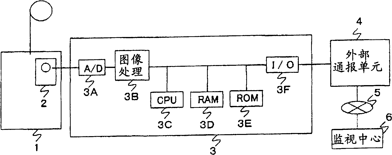
[0032] Hereinafter, the best form of the abnormality monitoring device in the elevator car for implementing the present invention will be described based on the drawings.

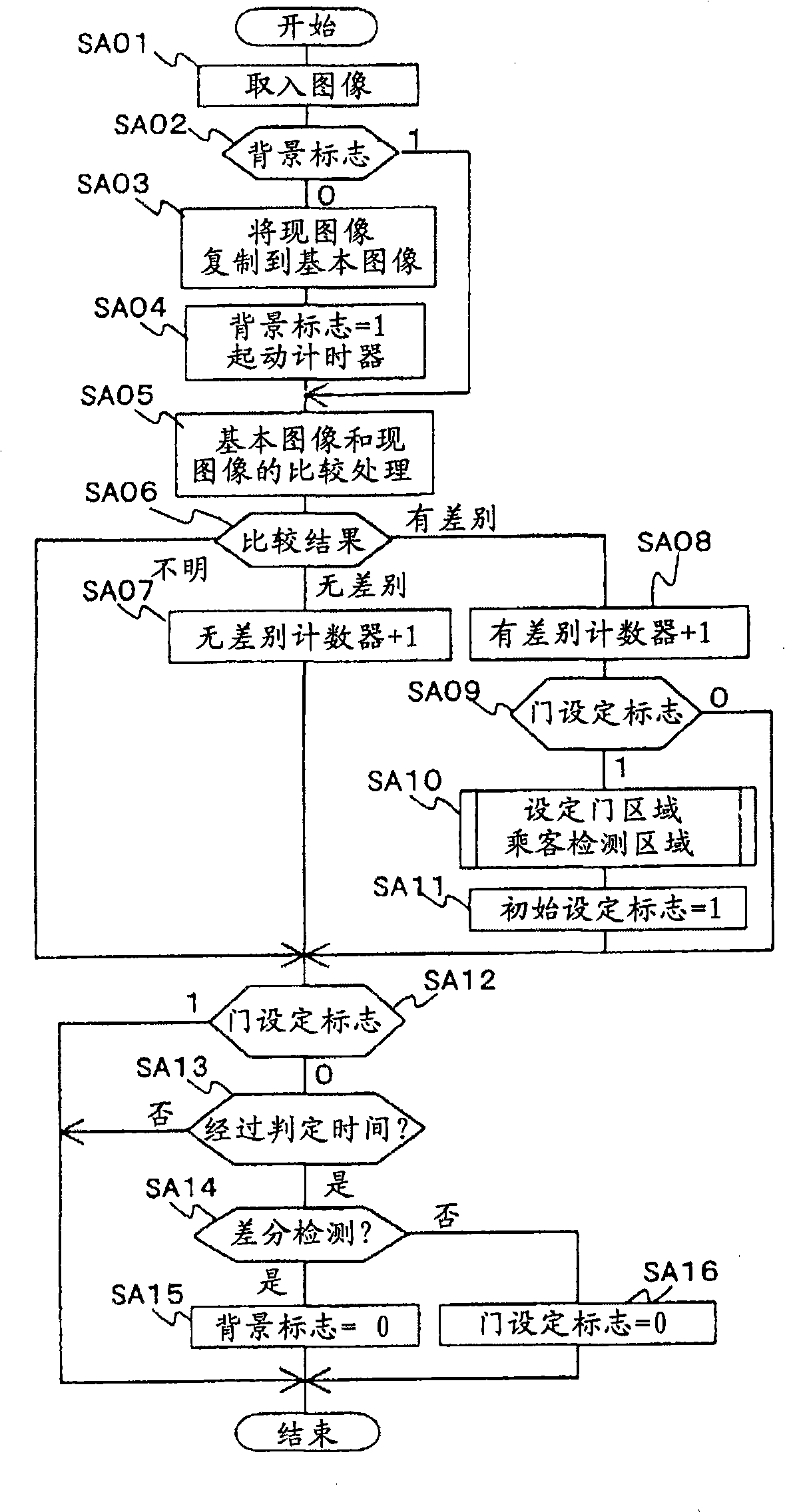
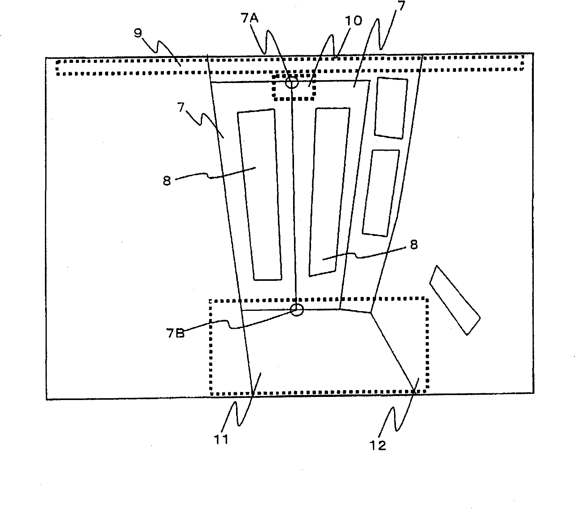
[0033] figure 1 It is a block diagram showing an embodiment of the abnormality monitoring device in the elevator car of the present invention, figure 2 Is a flowchart showing the initial setting process in this embodiment, image 3 It is a diagram for explaining the image comparison area in the image of the car in the present embodiment.Figure 4 It is a diagram for explaining the area setting process in this embodiment, Figure 5 Is a flowchart showing the abnormality detection process in this embodiment, Figure 6 It is a diagram for explaining camera abnormality detection due to pranks in this embodiment. Figure 7 It is a diagram for explaining staying detection in this embodiment.

[0034] Such as figure 1 As shown, this embodiment has: a camera 2 installed in the elevator car 1 to photograph the insid...


PUM


Abstract

The purpose of the invention is to provide an abnormal monitoring device in lift car; even the lift equipped with window glass on the door is able to monitor the abnormity without being affected by the light such as sunlight. The device has: an illumination light determination area equipped in the upper end area of camera image; a door lockage state determination area equipped near to the closed end of the upper part of the door; a passenger detecting area equipped in the lower area near the closed end of the lower part of the door; an illumination determination unit for comparing the illumination of the basic image and the illumination of the illumination light determination area of the image taken by the camera to determine the extinguished light of the illumination; a door lockage state determination unit for comparing the illumination of the basic image and the illumination of the door lockage state determination area in the current image to determine the lockage of the door; a passenger detecting unit for comparing the illumination of the basic image and the illumination of the passenger detecting area in the current image to determine whether there is passenger.

Description

Technical field [0001] The present invention relates to an abnormality monitoring device in an elevator car suitable for detecting abnormal conditions such as a fall caused by an ambush or disease in the elevator car. Background technique [0002] As this kind of prior art, it is proposed to use a camera to take an image of the elevator car, and to detect the presence or absence of passengers based on the image of the floor portion of the car, and to detect the presence or absence of passengers based on the movable portion of the car door that is not affected by the passengers in the image. The uppermost part of the image is used to detect the opening and closing of the car door. When it is detected that the passenger and the door are closed together for a certain period of time, or the door of the car door is detected to be closed, if the car door is not The image of the uppermost side wall affected by the passenger detects that the lighting lamp in the car is turned off, and th...

Claims


Application Information

Patent Timeline
IPC IPC(8): B66B3/00B66B5/00
Inventor 松井康作佐藤裕山口伸一朗高桥达法庄司久仁
Owner HITACHI BUILDING SYST CO LTD
Learn More