Hollow mold for filling cast-in-situ concrete

A technology of hollow carcass and cast-in-place concrete, which is applied to the on-site preparation of building components, formwork/formwork/work frame, structural elements, etc., which can solve the problems of low production efficiency, high cost, inconvenient production, etc., and achieve The effect of fast construction speed, simple construction and simple design

Inactive Publication Date: 2009-02-04
湖南邱则有专利战略策划有限公司
View PDF3 Cites 0 Cited by
  • Summary
  • Abstract
  • Description
  • Claims
  • Application Information

AI Technical Summary

Problems solved by technology

But when this kind of hollow carcass is applied to the floor construction, the hollow carcass cannot be accurately arranged in the middle layer of the floor, which affects the construction quality of the floor
For this reason, the patent No. is ZL01215092.4, and the name is "building component" utility model patent. The disclosed building component is a polyhedron, which can be hollow or solid. In order to ensure that this building component is applied to the floor It is arranged in the middle layer of the floor, and the outer wall of the polyhedron is provided with protruding legs, so that when the floor is poured, the legs can ensure that the hollow multi-faceted main cavity is just at the middle layer of the floor. , so as to better solve the above problems, but this kind of building components is inconvenient to make during production, the production efficiency is low, it is not convenient for assembly line production, and the cost is high

Method used


Image

  • Hollow mold for filling cast-in-situ concrete
  • Hollow mold for filling cast-in-situ concrete
  • Hollow mold for filling cast-in-situ concrete

Examples


Embodiment Construction

[0068] The present invention will be further described below in conjunction with the accompanying drawings and embodiments.

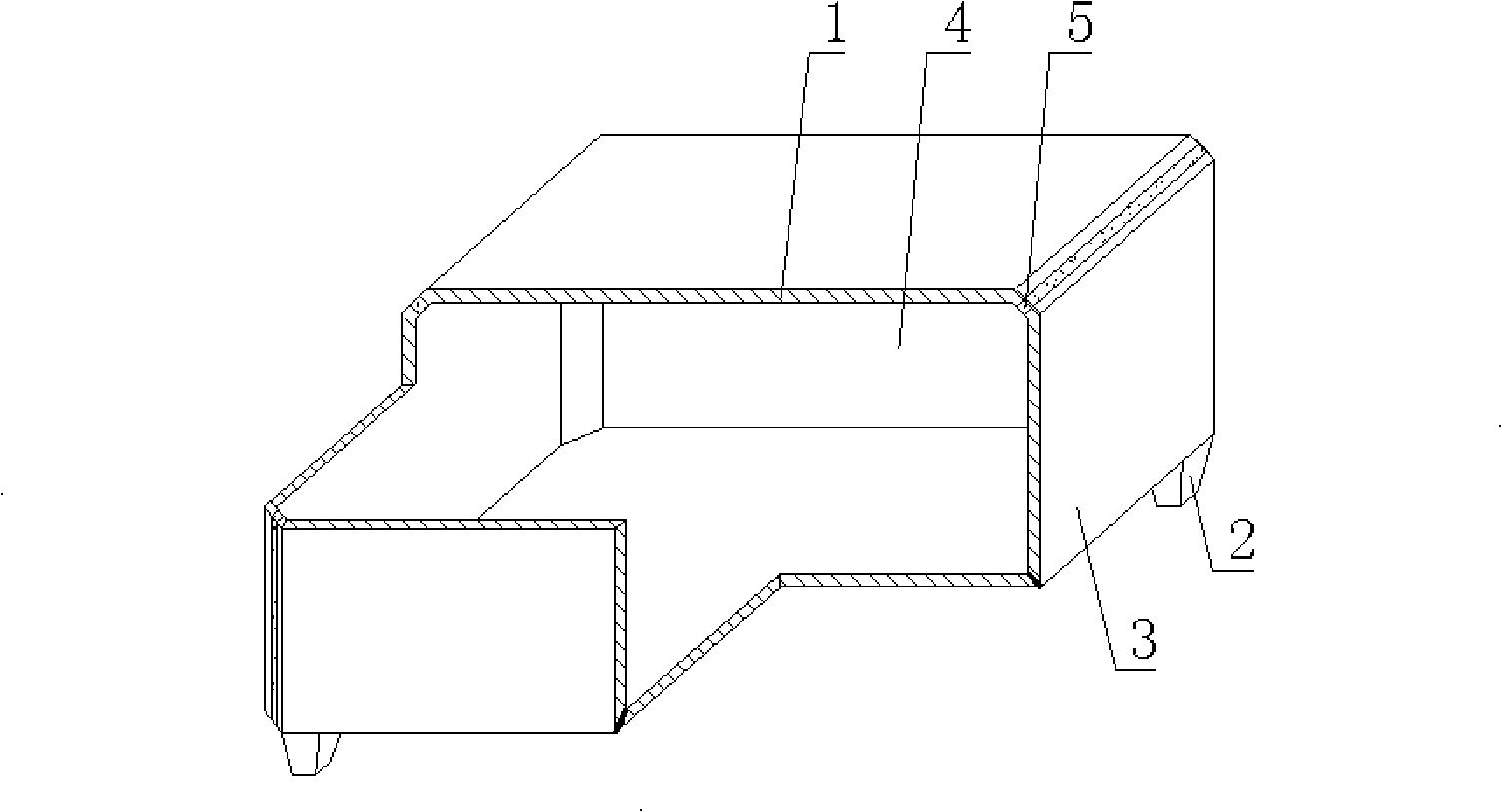
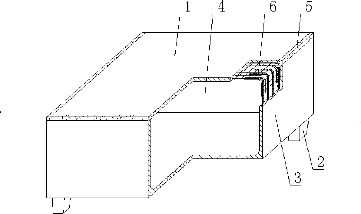
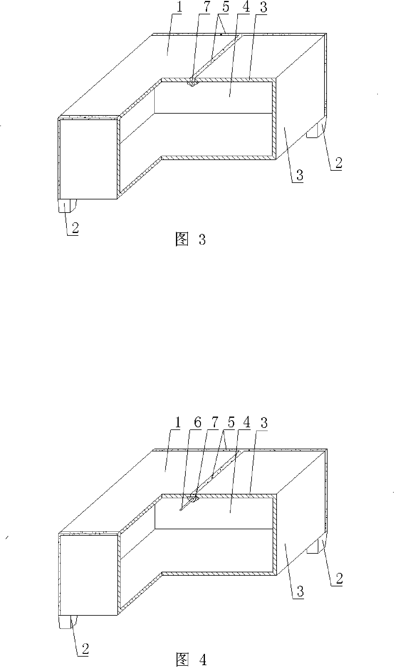
[0069] As shown in the accompanying drawings, the present invention includes a hollow carcass 1 and a support foot 2. The support foot 2 is arranged on the outer wall 3 of the bottom surface of the hollow carcass 1, and the outer wall 3 encloses the hollow carcass 1 with a cavity 4. Its characteristics All the outer walls 3 of the hollow carcass 1 are formed into embryos with cement slurry embryos, and the embryos of the connected or separated outer walls 3 are glued together at the joints, and the joints are the embryos. Side glued seams 5, at least two glued seams 5, after all the embryo body edges are seamed, a closed hollow carcass 1 is formed, and the supporting feet 2 are split feet, or there are overlapping fibers or mesh reinforcements at the seams 6; or there is a prefabricated member 7 at the bonding joint of the embryo body of the outer wall ...


PUM


Abstract

A hollow matrix for filling cast-in-place concrete includes a hollow matrix (1) and an arm brace (2). The arm brace (2) is arranged on the outside wall (3) of the bottom of the hollow matrix (1). The outside wall (3) circles to form the hollow matrix (1) with a cavity (4). The hollow matrix is characterized in that all the outside walls of the hollow matrix (1) use the completed base body of cement slurry. Joints among the base bodies of each connected or separated outside wall (3) are cemented. The joints are cementation joint closes (5) at the edges of the base body. The hollow matrix includes at least two cementation joint closes. After the base body edges are jointed, the closed hollow matrix (1) is formed. The arm brace is the brace of split type or the joints are provided with joint fiber or a net enhancer (6) or the cemented joint close of the base body of the outside wall (3) is provided with a prefabricated part (7) holding the base body or the prefabricated part (7) holding the base body is strip shape or the slurry base body of the outside wall (3) wraps the prefabricated part (7) holding the base body. The hollow matrix is applicable to the cast-in-place reinforced concrete or the hollow slab, the floor system, the roof system, the wall and the base soleplate of the prestressed concrete and bridges, which is especially applicable to hollow girderless floor system.

Description

[0001] This application is a divisional application of an invention patent application with an application date of September 2, 2004, an application number of 2004101552706, and a title of "a hollow matrix for filling cast-in-place concrete". (1) Technical field [0002] The invention relates to a hollow matrix for filling cast-in-place concrete. (2) Background technology [0003] At present, the cast-in-place concrete hollow floor is a widely used floor structure. The lightweight permanent tire molds filled in it include various hollow tubes and boxes, and the boxes are hollow or solid. For example, the patent No. ZL99249798.1, which the applicant applied for on November 29, 1999, is a utility model patent named "fiber-reinforced thin-walled member for reinforced concrete filling", which discloses a thin-walled formwork member, including an upper plate, The surrounding side walls, the lower bottom, and the upper plate, the surrounding side walls and the lower bottom form a ...

Claims


Application Information

Patent Timeline
Patent Type & Authority Applications(China)
IPC IPC(8): E04B5/36E04B5/48E04C5/00E04C5/16E04G15/06
Inventor 邱则有
Owner 湖南邱则有专利战略策划有限公司
Why Eureka
Try Eureka