Exposure driver circuit

A technology of driving circuits and resistors, used in optics, light sources, electric light sources, etc., can solve problems such as affecting the quality of dynamic images and reducing work efficiency.

Inactive Publication Date: 2009-02-04
HONG FU JIN PRECISION IND (SHENZHEN) CO LTD +1
View PDF0 Cites 0 Cited by
  • Summary
  • Abstract
  • Description
  • Claims
  • Application Information

AI Technical Summary

Problems solved by technology

For the camera, a longer shutter time will affect the quality of the dynamic image, and for the photography equipment of the SMT machine, it will reduce its work efficiency

Method used


Image

  • Exposure driver circuit
  • Exposure driver circuit
  • Exposure driver circuit

Examples


Embodiment Construction

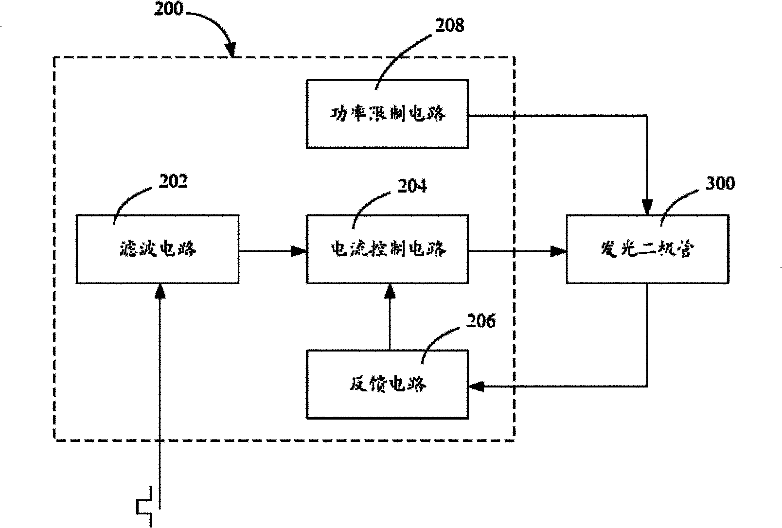
[0013] Such as image 3 As shown, the exposure driving circuit 200 disclosed in a preferred embodiment is used to receive a pulse signal, and then control the exposure operation of the LED 300 . The exposure driving circuit 200 includes a filter circuit 202 , a current control circuit 204 , a feedback circuit 206 and a power limiting circuit 208 . Wherein, the filter circuit 202 is used for filtering out the noise signal in the pulse signal. The current control circuit 204 is used to control the working current of the LED 300 so that the working current has a very high value within the time interval of the pulse signal. The operating current exceeds the maximum steady-state current of the LED 300 . In the high potential phase of the pulse signal, the feedback circuit 206 is used to provide a feedback signal to the current control circuit 204; and in the low potential phase of the pulse signal, the feedback circuit 206 is used to provide an inversion signal to the current con...


PUM


Abstract

An exposure drive circuit is used for receiving a pulse signal to provide the operating current surpassing the maximum steady-state current for a light-emitting diode. The exposure drive circuit comprises an operational amplifier, a metal field-effect transistor, a first resistor, a second resistor and a discharge power supply. The cocurrent input end of the operational amplifier receives the pulse signal, while the output end is electrically connected with the grid of the metal field-effect transistor. The drain electrode of the metal field-effect transistor is electrically connected with the light-emitting diode. The source electrode of the metal field-effect transistor is grounded through the first resistor and also electrically connected with the reverse input end of the operational amplifier through the second resistor. The discharge power supply is electrically connected with the light-emitting diode to supply the operating current for the light-emitting diode in the discharge form.

Description

technical field [0001] The invention relates to a photographing device, in particular to an exposure driving circuit of the photographing device. Background technique [0002] Photographic devices appear in various forms in people's production and life. For example, cameras in daily life, photography equipment for SMT (Surface Mount Technology) machines, etc. Such as figure 1 As shown, the photographing device 10 is used to capture an image of an object 999 to be photographed. The photography device 10 generally includes a controller 12 , an exposure driving circuit 14 , an LED array 16 and a photosensor 18 . When shooting, firstly, the controller 12 transmits relevant information about the lighting required for shooting to the exposure driving circuit 14 . The exposure driving circuit 14 drives the light-emitting diode array 16 to expose the object under test 999 according to the relevant information. Secondly, the controller 12 will control the photosensitive sensor 1...

Claims


Application Information

Patent Timeline
Patent Type & Authority Applications(China)
IPC IPC(8): G03B15/05H05B41/00
CPCH05B33/0818G03B15/05H05B33/0851G03B2215/05H05B45/37H05B45/12
Inventor 唐佩忠
Owner HONG FU JIN PRECISION IND (SHENZHEN) CO LTD
Why Eureka
Try Eureka