Connection method of transmission axle for precise transmission and bearing support part

A connection method and technology of supporting parts, which are applied in metal processing, metal processing equipment, manufacturing tools, etc., can solve problems such as increased production cost, unclean welding surface, economic loss, etc., and achieve simple manufacturing process, reduced production steps, and subsequent The effect of small processing volume

Inactive Publication Date: 2009-02-11
宋晓光
View PDF0 Cites 4 Cited by
  • Summary
  • Abstract
  • Description
  • Claims
  • Application Information

AI Technical Summary

Problems solved by technology

[0004] Before the patent application date of the present invention, the method used in the prior art for connecting the hollow body (109) and the bearing support part (111) of the transmission shaft, such as image 3 As shown, usually the bearing support portion (111) of the cylinder is welded at the two ends of the hollow body (109) to make it combined, but the shortcoming of this welding method is that the cylinder cannot be inserted in the center of the hollow body (109). The bearing support part (111) is welded later, and the cylindrical bearing support part (111) has been inserted into the hollow body (109) during welding, and the welding melt cannot flow into a certain depth evenly, so eccentricity and melt The axial end gap between the hollow body (109) and the cylindrical bearing support part (111) caused by the inability to flow into the interior cannot be used for precision transmission such as PDP panels and LCD panels when transmitting large screens.
[0005] After welding, the welding surface is not clean enough and deformed, requiring further processing
In order to solve these problems, additional processing is required after welding to increase the smoothness, which increases the production cost, and if there is no infrastructure to maintain the smoothness, many products will be thrown away, resulting in economic losses

Method used


Image

  • Connection method of transmission axle for precise transmission and bearing support part
  • Connection method of transmission axle for precise transmission and bearing support part
  • Connection method of transmission axle for precise transmission and bearing support part

Examples


Embodiment Construction

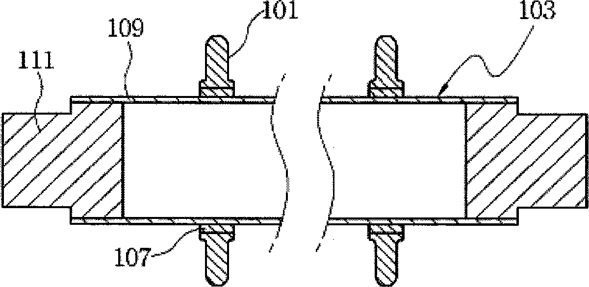
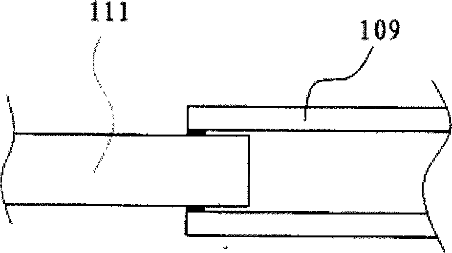
[0027] Combine below Figure 5 , Figure 6 The method for connecting the transmission shaft and the bearing supporting part used for precision transmission in the present invention is described in detail.

[0028] First fix the hollow main body 109 and the cylindrical bearing supporting part 111 on the rotating equipment respectively, and make the hollow main body 109 rotate, and the part of the hollow main body 109 that needs to be connected with the cylindrical bearing supporting part 111 is heated, and the heating depth should be lower than that of the cylindrical bearing supporting part 111. The insertion depth of the body bearing support part 111 is long, and the heating temperature should reach a plastic state that does not change the material properties of the hollow body 109, so that the insertion of the cylindrical bearing support part 111 is easy, and the heating is kept in the same direction to make the hollow body 109 The connecting part 30 is heated evenly; after...


PUM


Abstract

The invention discloses a method for the connection of a conveying shaft used for precision conveying and a bearing supporting part. The method comprises the following steps: (1) a hollow main body is fixed on rotating equipment; (2) the connecting part of the hollow main body is heated; (3) the cylindrical bearing supporting part is inserted into the hollow main body; (4) after the cylindrical bearing supporting part is inserted into the hollow main body, the cylindrical bearing supporting part and the hollow main body rotate together to form a central rotating shaft; (5) the hollow main body inserted into the cylindrical bearing supporting part is cooled down together, and after cooling, gapless matching is formed between the cylindrical bearing supporting part and the hollow main body; and (6) the outer surface of the connecting part of the hollow main body is processed. The hollow main body of the conveying shaft is connected with the cylindrical bearing supporting part without welding, so that the production steps are reduced; rotating insertion is adopted, so that the hollow main body of the conveying shaft and the cylindrical bearing supporting part have identical central shaft, the production process is simple, the subsequent processing amount is small, and the cost is low.

Description

technical field [0001] The invention relates to a method for manufacturing shaft parts, in particular to a method for manufacturing a transmission shaft of a transmission device. Background technique [0002] Usually, products with many production processes or complex structures and many parts need to be assembled or processed before the complete product comes out. In order to reduce bumps, scratches, or to improve efficiency, or to reduce handling personnel, generally Various production lines will be used to realize the transfer between processes, which requires various forms of transfer means, such as belt conveyors, suspension conveyors, etc., and when transferring relatively large and easily damaged plate-shaped components such as LCD panels Conveyor rollers are heavily used. Such as figure 1 In the transmission device shown, several transmission rollers (101) are installed at certain intervals on several transmission shafts (103) arranged in a row, and each roller (10...

Claims


Application Information

Patent Timeline
Patent Type & Authority Applications(China)
IPC IPC(8): B23P11/02
Inventor 胡淑英王淑青
Owner 宋晓光
Why Eureka
Try Eureka