Improved motor for pneumatic tools

A technology of pneumatic tools and motors, applied in the field of improved pneumatic tool motor devices, can solve problems affecting the performance and power of air motors, destroying bearing lubricating oil film, high-pressure air loss, etc., to achieve increased power, reduced loss, and utilization of air pressure Improved effect

Inactive Publication Date: 2009-02-11
ZHEJIANG UNIV
View PDF6 Cites 6 Cited by
  • Summary
  • Abstract
  • Description
  • Claims
  • Application Information

AI Technical Summary

Problems solved by technology

Because in order to reduce the friction between the shaft and the center hole of the cylinder head when the rotor rotates, a certain gap must be reserved between them, but the existence of the gap makes it easy for part of the high-pressure air in the cylinder to be lost from the gap, which reduces the air pressure and affects the output power. And the lost high-pressure airflow will destroy the lubricating oil film in the bearing, which will increase the friction of the bearing and shorten its life
These defects greatly affect the performance and power of the air motor

Method used


Image

  • Improved motor for pneumatic tools
  • Improved motor for pneumatic tools
  • Improved motor for pneumatic tools

Examples


Embodiment Construction

[0022] The present invention will be further described below in conjunction with drawings and embodiments.

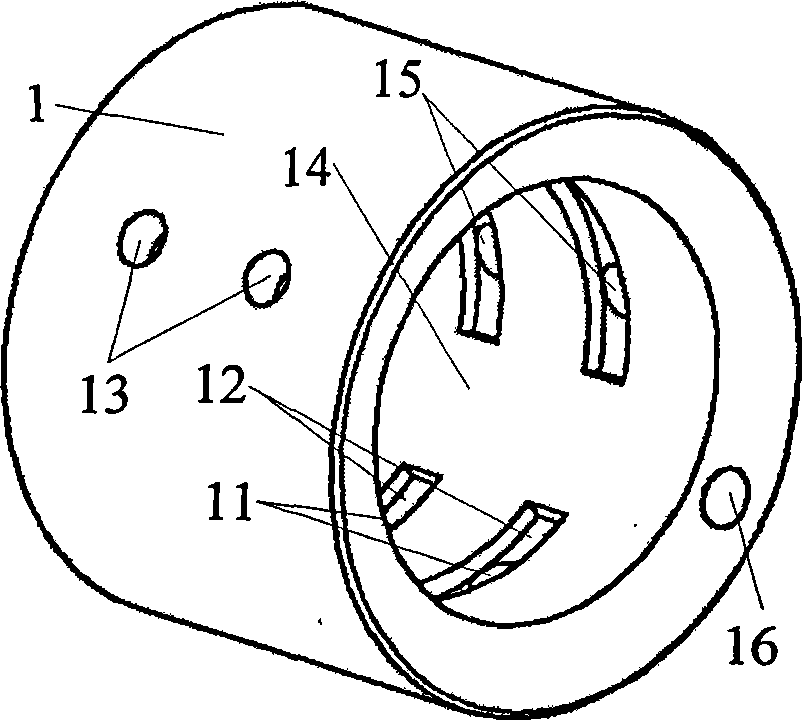
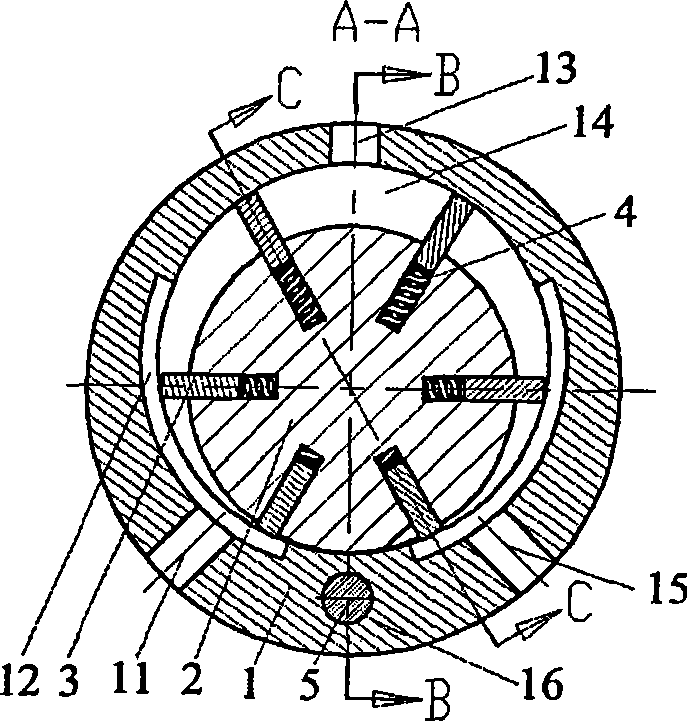
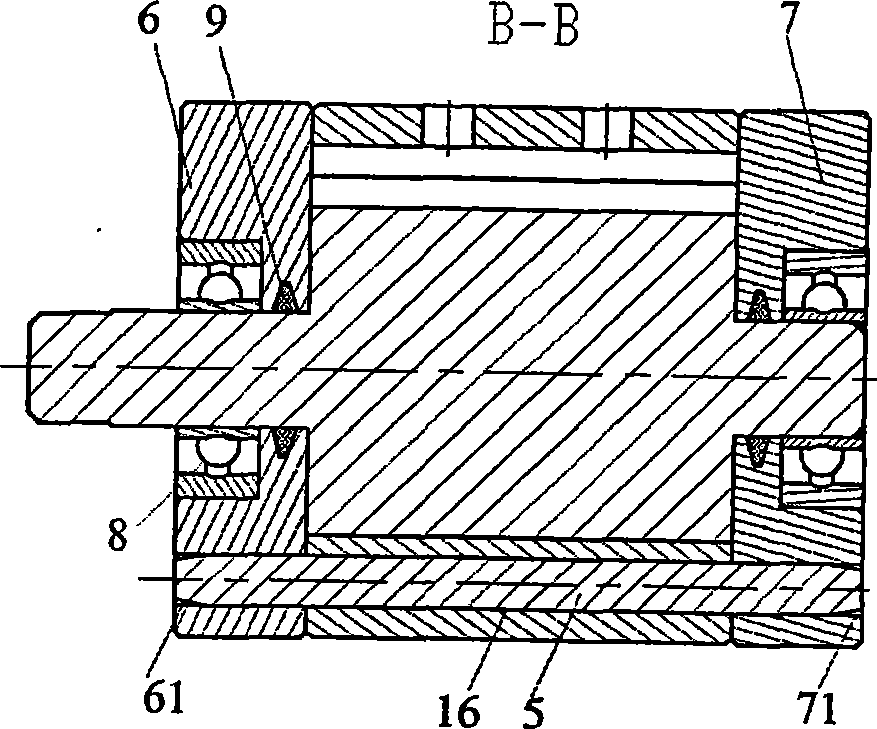
[0023] refer to figure 1 ~As shown in Fig. 5, the present invention includes a cylinder 1 and a rotor 2 having two main exhaust holes 13, and the rotor 2 is housed in the cylinder cavity 14 of an eccentric circular hole, and the rotor 2 is radially and equally divided into six grooves , each groove is equipped with blades 3, the two ends of the cylinder are sealed by the front cylinder cover 6 and the rear cylinder cover 7, and the cylinder cover is provided with bearings 8 to support the rotation of the rotor 2. The bottom of each blade 3 is provided with two cylindrical small bosses 31 on the end surface close to the bottom of the slot, and two small blind holes 21 are provided on the bottom surface of the rotor slot. One end of the spring 4 is inserted into the small blind holes 21, and the other end is covered Live small boss 31, have two air holes 11,15 symmetrica...


PUM


Abstract

The present invention discloses an improved pneumatic tool motor device which comprises a cylinder and a rotor. A cylinder inner cavity of an eccentric circular hole is equipped with the rotor. The rotor is divided into six slots along the radial direction. Every slot is equipped with a vane. A cylinder cover is provided with a bearing supporting the rotor to rotate. The bottom of the vane is provided with two columnar lug bosses at the end face near the slot bottom. The bottom surface of the rotor is provided with two small blind holes. One end of a spring is plugged in the small blind hole, and the other end hitches the small lug bosses. Two arc air current guide slots are symmetrically arranged at the inner wall at the lower end of the cylinder inner cavity and are respectively communicated with air holes at the corresponding side. Obturating rings are arranged at the position of neck journals at two ends of the rotor for improving the leak tightness. The improved motor device can ensure that high pressure air entering the cylinder is all used for pushing the rotor to rotate; the air enters through the lateral wall, so the gas flowing resistance is reduced, and the power of the motor device is improved greatly.

Description

technical field [0001] The present invention relates to a motor device of an air tool, in particular to an improved motor device of an air tool. Background technique [0002] Pneumatic tool motor device is a device that converts the air pressure energy of high-pressure air into mechanical energy. It is the driving part of pneumatic tools. Usually, the blade rotor in the cylinder is driven by high-pressure air to achieve rotary motion. It is widely used in wind pullers, splitters, and wind mills. And pneumatic tools such as pneumatic drills. [0003] In the current air tool motor device, the high-pressure air needs to be divided after entering the cylinder, and part of the air pressure can be used to push out the blades, so that the blades can withstand the inner wall of the cylinder and divide the cylinder into several air-containing areas, and part of the air pressure can be used in the above-mentioned air-containing areas. A pressure differential is formed to drive the ro...

Claims


Application Information

Patent Timeline
Patent Type & Authority Applications(China)
IPC IPC(8): F01C1/344
Inventor 邱清盈姚振农冯培恩
Owner ZHEJIANG UNIV
Why Eureka
Try Eureka