Eureka AIR delivers breakthrough ideas for toughest innovation challenges, trusted by R&D personnel around the world.

Optimal phasing of charges in a perforating system and method

a perforating system and optimal technology, applied in the field of perforation guns, to achieve the effect of efficient oil and gas flow rates

Inactive Publication Date: 2017-09-28
GEODYNAMICS
View PDF6 Cites 1 Cited by
  • Summary
  • Abstract
  • Description
  • Claims
  • Application Information

AI Technical Summary

Benefits of technology

The patent aims to provide a method for reducing energy loss and improving the efficiency of injecting fluids into a perforation tunnel. By using a minimum number of shots per foot, the method aims to achieve a maximum fracture length with minimal tortuosity. Additionally, the patent seeks to improve the probability of perforating within a specific region and to optimize the phasing of charges in the perforating gun for maximum perforation and fracturing efficiency.

Problems solved by technology

However, horizontal wellbores are often deviated as much as 100 ft in any direction over the length of 3 miles.
The charges in the gun may or may not be optimally phased when perforating.
If all perforations are involved, and the perforations are shot with 0°, 60°, 90°, 120°, or 180° phasing, multiple fracture planes may be created, leading to substantial near wellbore friction and difficulty in placing the planned fracturing treatment.
However, the chances of perforating in an upward and downward direction are low when the well casing is deviated and the perforating gun is not horizontal.
There is an accuracy issue of positioning the guns (orienting) with respect to the up / down vector.
Field results indicate that even with orientation of the guns, operational issues can cause perforations in a non-preferred region.
However, since the wells are not perfectly horizontal and in most case deviated, the gun (0411) may be rotated as illustrated in FIG. 4 (0420) and the charges (0404) may be perforating into the high compression region or sideways and produce ineffective fracture treatment.
Some of the perforation tunnels cause energy and pressure loss during fracturing treatment which reduces the intended pressure in the fracture tunnels.
Therefore, if any perforation does not participate, then the incremental rate per perforation of every other perforation is increased, resulting in higher perforation friction.
The phase angle is set based on the minimization.” However, U.S. Pat. No. 7,303,017A does not teach an optimal phasing of the charges in the bank so that charges perforate within desired perforation angles in a low compression region especially for a deviated well.
The prior art as detailed above suffers from the following deficiencies:Prior art perforation phasing systems do not provide for efficiently reducing tortuosity and energy loss in a perforation tunnel with minimum number of shots per foot.Prior art perforation phasing systems do not provide for longer extension of fractures which have minimal tortuosity with minimum number of shots per foot.Prior art perforation phasing systems do not provide for the highest and optimal injection rate per perforation tunnel so that a maximum fracture length is realized with minimum number of shots per foot in a cluster.Prior art perforation phasing systems do not provide for achieving a probability greater than 50% for perforating within +−15° of the upward and downward low compression region.Prior art perforation phasing systems do not provide for an optimal phasing of the charges in the perforating gun per cluster in order to achieve maximum perforation and fracturing efficiency.Prior art perforation phasing systems do not have an optimal statistical chance of perforation placement when less than or more than 6 shots are placed in a cluster.
While some of the prior art may teach some solutions to several of these problems, the core issue of reacting to unsafe gun pressure has not been addressed by prior art.

Method used


Image

  • Optimal phasing of charges in a perforating system and method
  • Optimal phasing of charges in a perforating system and method
  • Optimal phasing of charges in a perforating system and method

Examples


Embodiment Construction

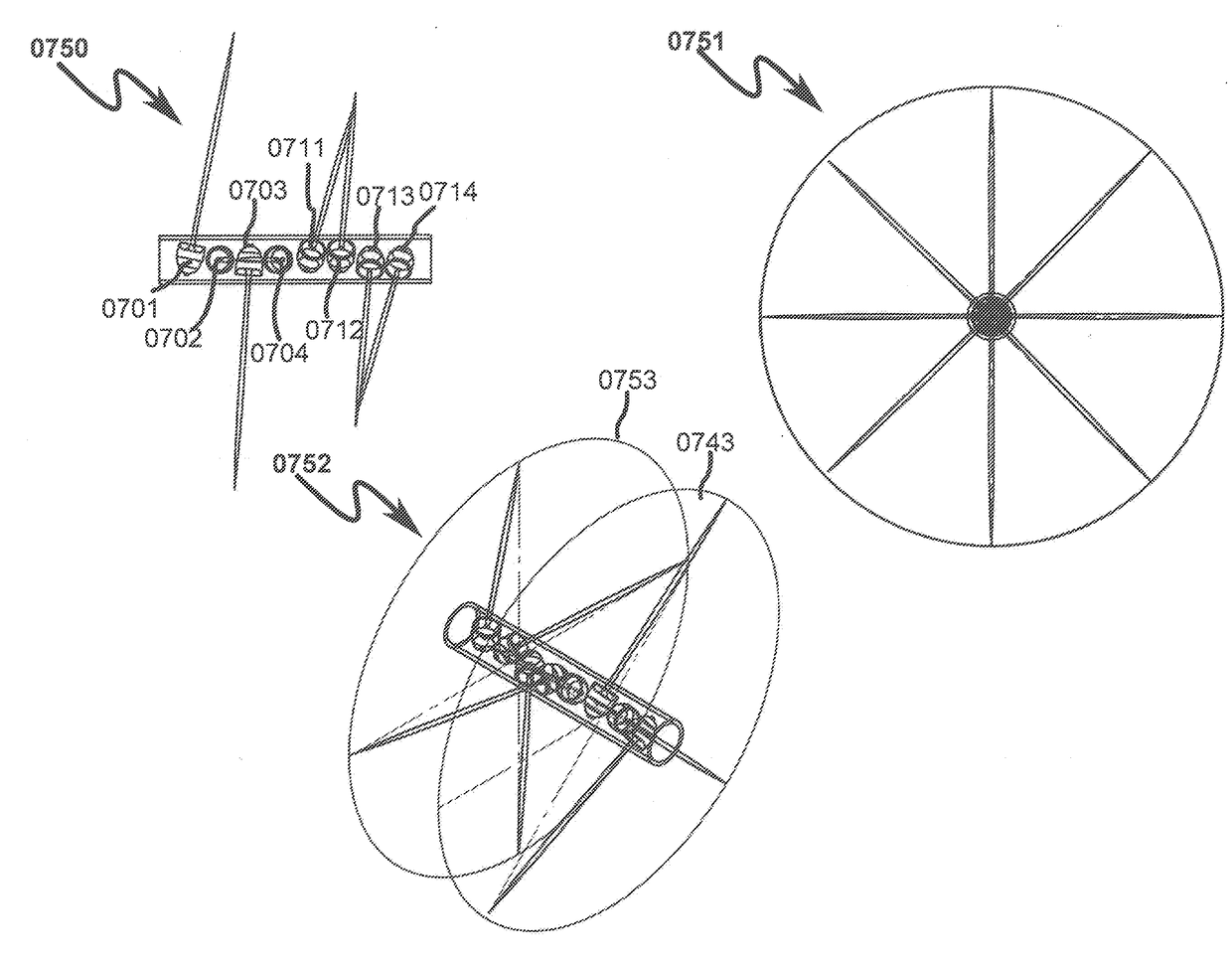
[0068]While this invention is susceptible of embodiment in many different forms, there is shown in the drawings and will herein be described in detailed preferred embodiment of the invention with the understanding that the present disclosure is to be considered as an exemplification of the principles of the invention and is not intended to limit the broad aspect of the invention to the embodiment illustrated.

[0069]The numerous innovative teachings of the present application will be described with particular reference to the presently preferred embodiment, wherein these innovative teachings are advantageously applied to the particular problems of optimal phasing perforating gun system and method. However, it should be understood that this embodiment is only one example of the many advantageous uses of the innovative teachings herein. In general, statements made in the specification of the present application do not necessarily limit any of the various claimed inventions. Moreover, so...


PUM


Abstract

An optimal perforating gun method for accurate perforation in a deviated / horizontal wellbore is disclosed. The method includes a gun string assembly (GSA) deployed in a wellbore with shaped charges arranged in rows in a cluster and a total number of the shaped charges is equal to a total number of the rows. A total number of charges for each cluster in a stage is selected with the best statistical probability for a desired number of perforations in the cluster. The number of charges and the number of rows per each cluster in a stage is optimized such that there is a maximum probability of perforating into a low compression region in an upward and downward direction.

Description

CROSS REFERENCE TO RELATED APPLICATIONS[0001]This application is a continuation in part of U.S. application Ser. No. 15 / 080,251, filed Mar. 24, 2016, the disclosure of which is fully incorporated herein by reference.FIELD OF THE INVENTION[0002]The present invention relates generally to perforation guns that are used in the oil and gas industry to explosively perforate well casing and underground hydrocarbon bearing formations, and more particularly to arranging shaped charges in rows in a cluster for explosively perforating a well casing and its surrounding underground hydrocarbon bearing formation.PRIOR ART AND BACKGROUND OF THE INVENTIONPrior Art Background[0003]During a well completion process, a gun string assembly is positioned in an isolated zone in the wellbore casing. The gun string assembly comprises a plurality of perforating guns coupled to each other either through tandems or subs. The perforating gun is then fired, creating holes through the casing and the cement and in...

Claims


Application Information

Patent Timeline
IPC IPC(8): E21B43/116E21B43/26
CPCE21B43/116E21B43/26E21B43/119
Inventor HARDESTY, JOHN TWESSON, DAVID S
Owner GEODYNAMICS
Why Eureka
Eureka Blog
Learn More