Control circuit for high brightness LED lamp

A technology for controlling circuits and LED lamps, applied in the direction of lamp circuit layout, circuit layout, electric light source, etc., can solve the problems of affecting the uniformity of light distribution and the inability to reduce voltage, and achieve the effect of meeting the requirements of halving the brightness and saving energy

Inactive Publication Date: 2009-02-11
朱敬华
View PDF0 Cites 4 Cited by
  • Summary
  • Abstract
  • Description
  • Claims
  • Application Information

AI Technical Summary

Problems solved by technology

[0002] At present, lighting fixtures such as street lamps and spotlights on the market all use a point light source plus a reflector, and use the reflector to achieve the effect of light distribution. Due to the light-emitting principle of high-voltage sodium lamps, they cannot be used at reduced voltage. To reduce the brightness of the time period, two bulbs or two-stage ballasts must be used, but this will affect the uniformity of light distribution. With the development of LED green light sources, various manufacturers have introduced lighting appliances that use LEDs as light sources, including LED street lamps, LED spotlights, etc. also need a circuit to control the LED light source in order to meet the requirements of reducing brightness during off-peak hours.

Method used


Image

  • Control circuit for high brightness LED lamp
  • Control circuit for high brightness LED lamp
  • Control circuit for high brightness LED lamp

Examples


Embodiment 1

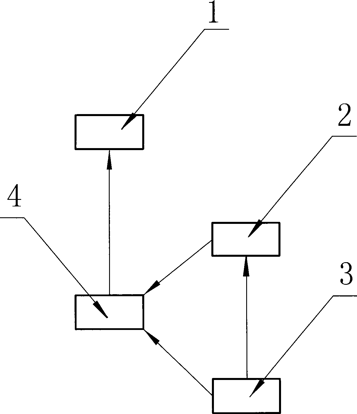
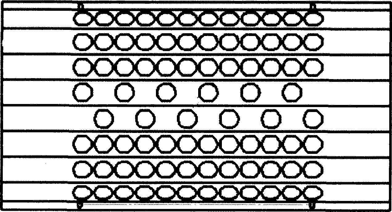
[0025] Reduce the number of lit particles, and control the enable terminal of multiple LED drive circuits (the chip has an Enable / Disable function). Through the Enable / Disable function of the chip, you can directly control each output circuit to be ON or OFF; set the time through the time timing control circuit. Set a certain period of time to the "full off" state, set each output circuit to "OFF" through the chip, and the street lights will not light; set a certain period of time to the "on" state, and set each output circuit through the chip When the circuit is "ON", the street lamp is on; set a certain period of time as "partially off" state, and set some output circuits to "OFF" through the chip, then some LEDs of the street lamp are off and some are on.

Embodiment 2

[0027] To reduce the lit particles, control the enable terminal of the LED drive circuit (the chip does not have the Enable / Disable function). Each drive circuit is connected to one relay, and the LED drive circuit is controlled through the relay; the time is set through the time timing control circuit. Set a certain period of time to the "full off" state, each Relay is set to "OFF", each LED drive circuit is turned off, and the street lights will not light; set a certain period of time to "on" state, each Relay If it is set to "ON", the LED drive circuits of each channel are turned on, and the street lamps are turned on; if a certain period of time is set to "partially off" state, some Relays are set to "OFF", and the LEDs connected to them When the drive circuit is turned off, some LEDs of the street lamp are turned off and some are turned on.

Embodiment 3

[0029] Reduce the drive current, control the resistance value of the LED drive circuit to change its drive current. Each drive circuit has two different groups of resistors, and the current flowing through the LED is controlled by switching the resistance value; the time timing control circuit is used to set the time and control the selection of the electric group. Set a certain period of time as the "full bright" state, the time timing control circuit will control each drive circuit to select the resistance that makes the LED work normally, and the LED will work normally; set a certain period of time as the "half bright" state, the time timing The control circuit will control each drive circuit to select another set of resistors, so that the current flowing through the LED is lower than the normal working current (the current should be based on the required luminous flux).


PUM


Abstract

The invention discloses a control circuit of a high brightness LED lamp, which comprises an optical module of the high brightness LED, a driving circuit of the high brightness LED and a high brightness LED lamp that consists of sequentially connected switch powers; the high brightness LED lamp is provided with a high brightness LED driving control circuit, which is convenient to control the brightness of LED illuminating equipment, satisfy the energy-saving requirement that the brightness is halved during the off-peak period without influencing the light distribution uniformity; the control circuit of the high brightness LED lamp can be widely used in the LED illuminating equipment such as high brightness LED street lamps, high brightness LED projectors, etc.

Description

technical field [0001] The invention relates to the field of lighting control circuits, in particular to a control circuit for high-brightness LED lamps. technical background [0002] At present, lighting fixtures such as street lamps and spotlights on the market all use a point light source plus a reflector, and use the reflector to achieve the effect of light distribution. Due to the light-emitting principle of high-voltage sodium lamps, they cannot be used at reduced voltage. To reduce the brightness of the time period, two bulbs or two-stage ballasts must be used, but this will affect the uniformity of light distribution. With the development of LED green light sources, various manufacturers have introduced lighting appliances that use LEDs as light sources, including LED street lamps, LED spotlights, etc. also need a circuit to control the LED light source in order to meet the requirements of reducing brightness during off-peak hours. Contents of the invention [000...

Claims


Application Information

Patent Timeline
Patent Type & Authority Applications(China)
IPC IPC(8): F21V23/00H05B37/02F21Y101/02F21Y115/10
Inventor 朱敬华
Owner 朱敬华
Why Eureka
Try Eureka