
LED lamp and heat radiation structure thereof

A technology of LED lamps and heat dissipation structures, applied in lighting and heating equipment, cooling/heating devices of lighting devices, lighting devices, etc., can solve the problems of increased volume and area, insufficient heat dissipation capacity, and inability to significantly reduce thermal resistance, etc. Achieve the effects of reducing thermal resistance, improving thermal conductivity and heat dissipation performance

Inactive Publication Date: 2009-02-11
BEIJING ZHONGQING MICRO ELECTRIC TECH
View PDF0 Cites 7 Cited by
  • Summary
  • Abstract
  • Description
  • Claims
  • Application Information

AI Technical Summary

Problems solved by technology

The higher the power of the LED, the greater the heat generation, and the heat generated by a single high-power LED and an integrated high-power LED is very concentrated. At present, the heat sink made of metal materials with good heat dissipation performance such as aluminum and copper is generally used. Its heat dissipation capacity is obviously insufficient, and increasing the volume and area can no longer significantly reduce the thermal resistance, which makes the heat energy emitted by the LED unable to be conducted and released in time, which seriously affects the work of the LED.

Method used


Image

  • LED lamp and heat radiation structure thereof
  • LED lamp and heat radiation structure thereof
  • LED lamp and heat radiation structure thereof

Examples


Embodiment Construction

[0024] The present invention will be described in detail below in conjunction with the accompanying drawings and specific embodiments.

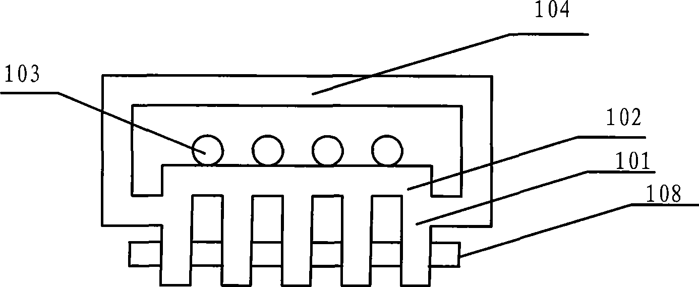
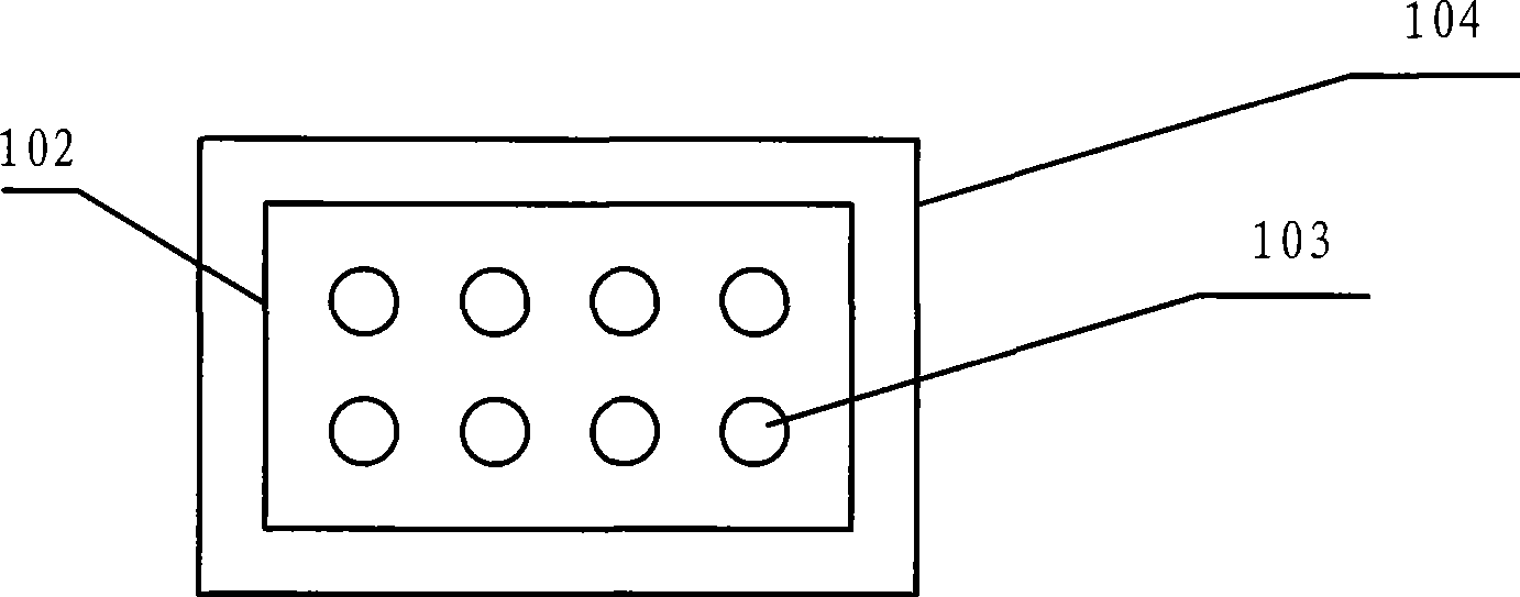
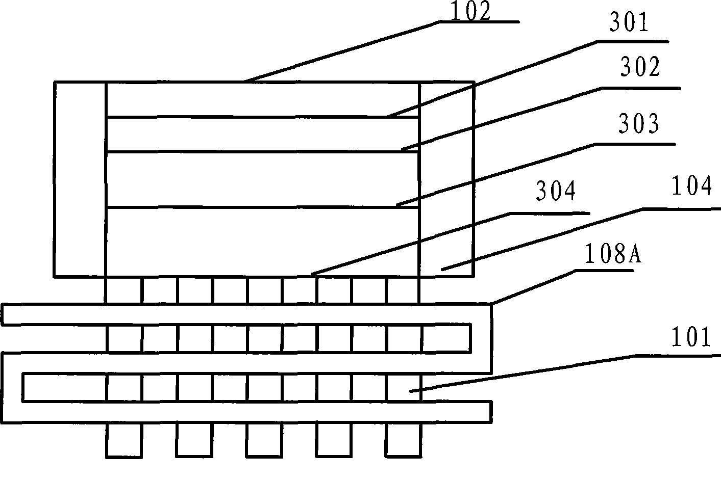
[0025] as attached figure 1 and figure 2 As shown, the present invention provides an LED lamp, which includes a lamp housing 104, a heat sink 101, a heat absorption tube 108, and a circuit board substrate 102. The heat sink 101 is fixed below the circuit substrate 102, and the circuit board substrate 102 is fixed inside the lamp housing 104; the lamp housing 104, the heat sink 101 and the circuit board substrate 102 are integrally formed of the same material; the heat absorption tube 108 is installed on the heat sink 101. The lamp housing 104, the heat sink 101 and the circuit board substrate 102 are integrated into one body, which is very conducive to the dissipation of heat; LED light-emitting diodes are fixed on the circuit board substrate 102, and other electronic components are connected to the circuit board substrate 102 by welding. ...


PUM


Abstract

The invention discloses an LED lamp and the heat dissipating structure thereof, which comprise a heat dissipating fin and an endothermic tube that is arranged on the heat dissipating fin and is used for absorbing the heat on the heat dissipating fin quickly. The heat dissipating fin is provided with a through hole, and the endothermic tube is arranged in the through hole and is closed circulation reciprocating structure, the tube is provided with liquid. The closed circulation reciprocating structure comprises at least one of the following closed circulation reciprocating structures: the capital letter B font, the capital letter O font and square hole shape. The liquid is used for carrying out the circulation movement in the endothermic tube during the heating. A lamp shell, the heat dissipating fin and the substrate of a circuit board are a whole molded by the integral forming of the same material, which reduces the number of formed thermal resistances, meanwhile, the seamless connection of an insulation oxide layer and the heat dissipating fin can reduce the heat resistance value greatly; by adopting the method of combining the heat dissipation of the endothermic tube and the heat dissipating fin, the heat conducting and dissipating performances can be increased greatly, and the LED lamp and the heat dissipating structure thereof are particularly suitable for the heat dissipation of light sources of high power LEDs.

Description

technical field [0001] The invention relates to a heat dissipation structure, in particular to an LED lamp and a heat dissipation structure thereof. Background technique [0002] With the development of semiconductor lighting technology, LED has gradually developed from traditional low power to single high power and integrated high power. However, LED can only work normally under a certain temperature. The higher the power of the LED, the greater the heat generation, and the heat generated by a single high-power LED and an integrated high-power LED is very concentrated. At present, the heat sink made of metal materials with good heat dissipation performance such as aluminum and copper is generally used. Its heat dissipation capacity is obviously insufficient, and increasing the volume and area can no longer significantly reduce the thermal resistance, which makes the heat energy emitted by the LED unable to be conducted and released in time, which seriously affects the work ...

Claims


Application Information

Patent Timeline
IPC IPC(8): F21V29/00H01L23/427F21Y101/02F21V29/51F21V29/74F21Y115/10
Inventor 商松
Owner BEIJING ZHONGQING MICRO ELECTRIC TECH
Learn More