Liquid crystal display panel

A liquid crystal display panel and data line technology, applied in the direction of static indicators, instruments, etc., can solve the problems of inconsistency in brightness and darkness of pixels and affect the display quality, and achieve the effect of avoiding inconsistency in brightness and darkness and improving the display effect

Active Publication Date: 2009-02-11
KUSN INFOVISION OPTOELECTRONICS
View PDF0 Cites 13 Cited by
  • Summary
  • Abstract
  • Description
  • Claims
  • Application Information

AI Technical Summary

Problems solved by technology

In this way, the signal charging amount of the sub-pixel electrode connected to the data line D1 and the data line Dn is more than the signal charging amount of the other sub-pixel electrodes, which will cause a row of pixels connected to the data line D1 or Dn to be different from other positions during display. Inconsistencies in the brightness and darkness of the pixels, which in turn affect the display quality

Method used


Image

  • Liquid crystal display panel
  • Liquid crystal display panel
  • Liquid crystal display panel

Examples


Embodiment Construction

[0039] In order to make the above-mentioned objects, features and advantages of the present invention more obvious and understandable, the specific embodiments of the present invention will be described in detail below with reference to the accompanying drawings. Of course, the present invention is not limited to this specific embodiment, and general substitutions well known to those of ordinary skill in the art are undoubtedly covered by the protection scope of the present invention.

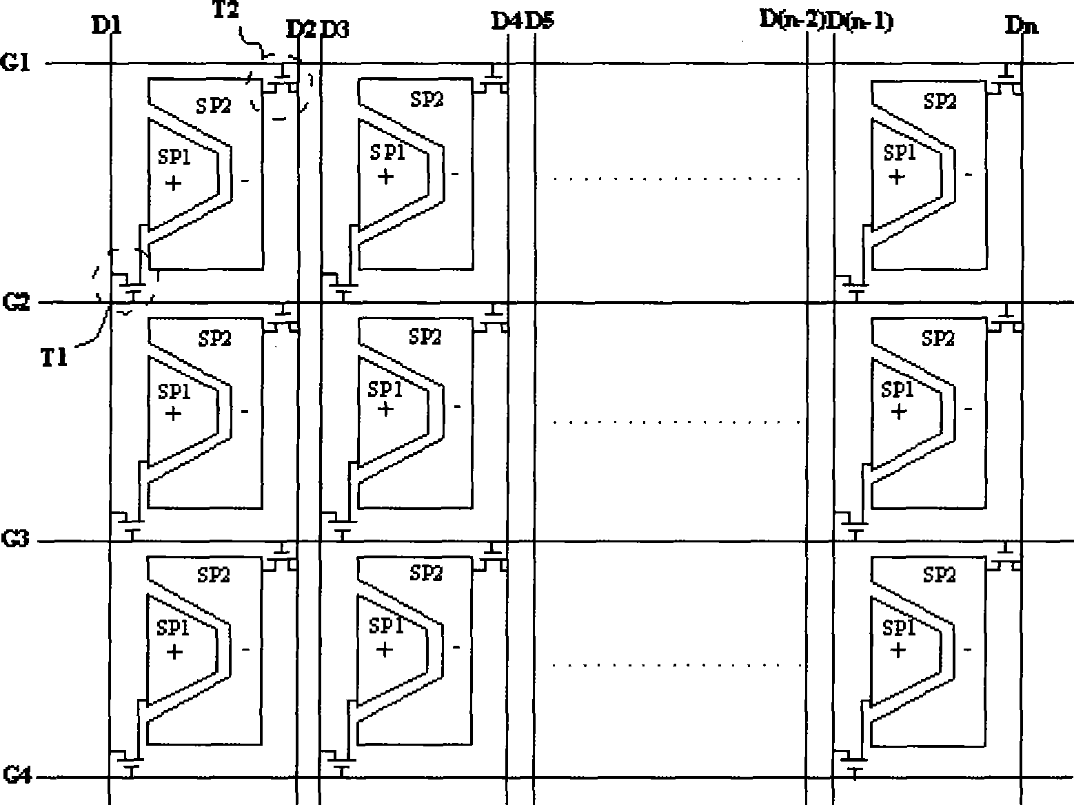
[0040] Since the arrangement structure of the left and right sides of the liquid crystal display array substrate adopting this structure is basically the same, only the structure of the left part of the liquid crystal display array substrate is taken as an example for description, and the structure of the right part is not described in detail.

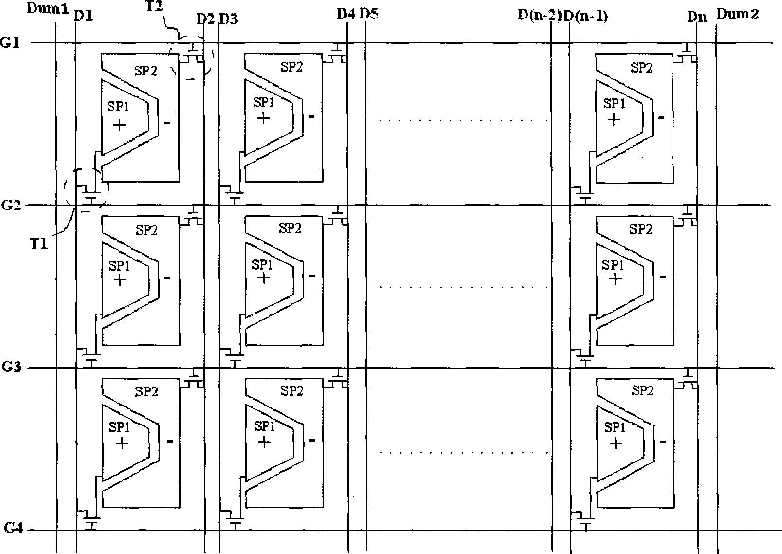
[0041] See figure 2 , Showing the structure diagram of the pixel array of the liquid crystal display panel in the first embodiment of the present invention...


PUM


Abstract

The invention relates to a liquid crystal display (LCD) panel structure, which includes a plurality of scan lines, a plurality of data lines intersected with the scan lines to define a plurality of pixel areas a plurality of pixels, and pixel arrays formed in the pixel areas and arranged in the shape of a matrix to form a pixel array, wherein a virtual data line is arranged near the outmost data line of the pixel areas, thereby ensuring that the signal transmission delay time constants of the outmost data line of the pixel areas and the data lines inside the pixel matrix are basically the same, so as to avoid the discrepancy phenomenon of the brightness on the two sides of the panel in the prior art, and improve the displaying effect of the LCD panel.

Description

Technical field [0001] The present invention relates to the field of liquid crystal display devices, in particular to a liquid crystal display panel with higher display effects. Background technique [0002] With the wide application of liquid crystal displays, people have higher and higher requirements for liquid crystal displays, such as high brightness, high contrast, high resolution, high color saturation, and fast time response. Generally, traditional LCD displays mostly display with narrow viewing angles. The best picture can only be viewed on the front of the LCD. If viewed at a larger viewing angle, color distortion will occur, and even bright and dark displays will occur. The gray inversion phenomenon in which the state is reversed. The viewing angle of the liquid crystal display is determined by the liquid crystal display panel. Therefore, how to increase the viewing angle of the liquid crystal display panel has become an important issue urgently needed to be solved by ...

Claims


Application Information

Patent Timeline
Patent Type & Authority Applications(China)
IPC IPC(8): G02F1/133G09G3/36
Inventor 钟德镇廖家德邱郁雯乔艳冰孔祥建
Owner KUSN INFOVISION OPTOELECTRONICS
Why Eureka
Try Eureka