Storage system

A storage system and non-volatile memory technology, applied in the field of storage area allocation, can solve problems such as a leap in the amount of data

Active Publication Date: 2009-02-11
HITACHI LTD
View PDF2 Cites 11 Cited by
  • Summary
  • Abstract
  • Description
  • Claims
  • Application Information

AI Technical Summary

Problems solved by technology

In addition to such information growth, long-term records of corporate business activities (transaction information, emails, etc.) The increase in customer requirements for storage, etc., has led to a dramatic increase in the amount of data to be stored on storage devices, resulting in a large-scale storage system

Method used


Image

  • Storage system
  • Storage system
  • Storage system

Examples


no. 1 example

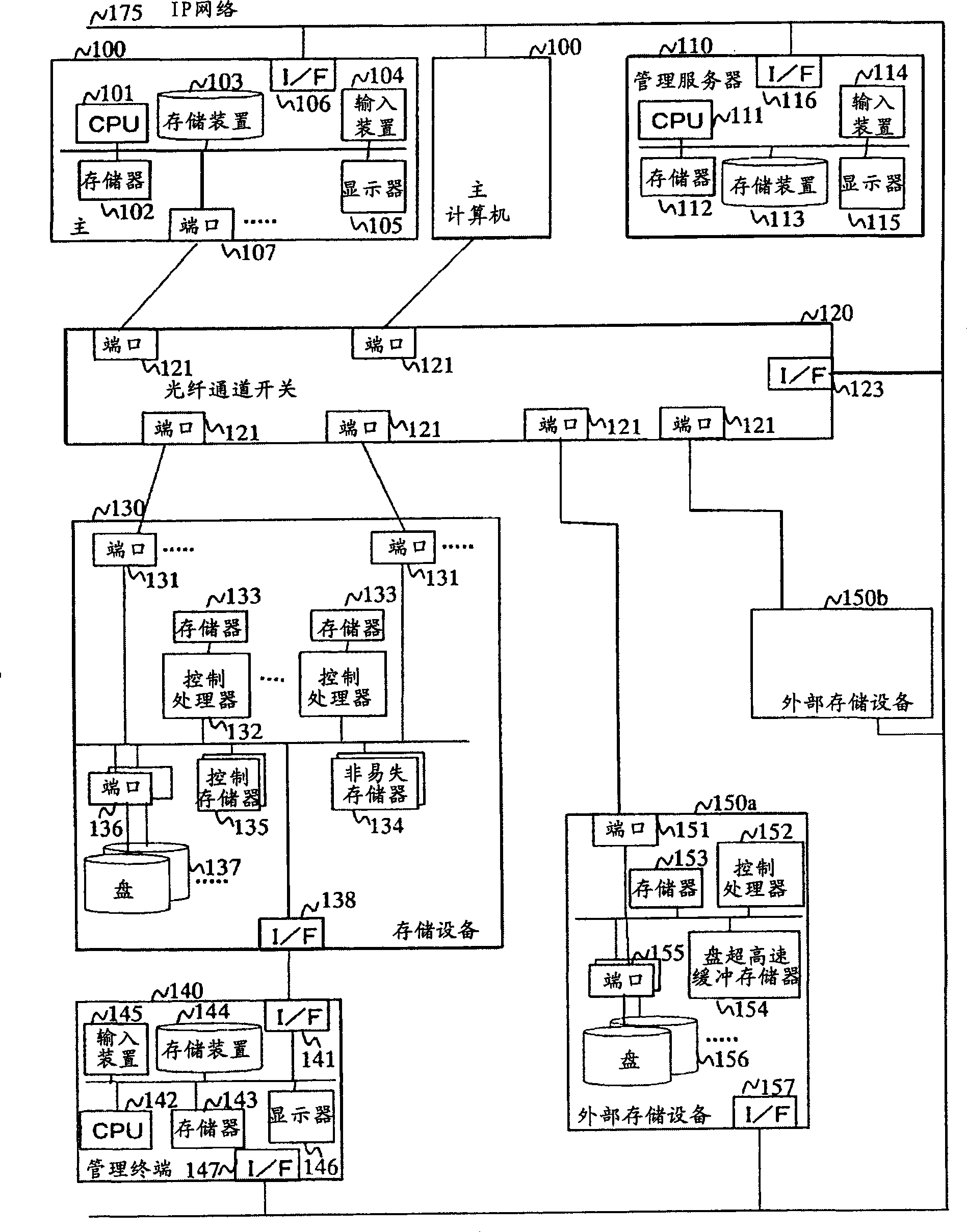
[0076] First refer to Figure 1 to Figure 13 and Figure 19 and Figure 20 The first embodiment will be described. figure 1 It is a diagram showing an example of a hardware configuration of a computer system using the first embodiment of the present invention.

[0077] The computer system includes one or more host computers 100, management server 110, fiber channel switch 120, storage device 130, management terminal 140, external storage devices 150a and 150b (collectively referred to as external storage devices 150). The host computer 100 , the storage device 130 and the external storage device 150 are respectively connected to the port 121 of the fiber channel switch 120 through ports 107 , 131 , and 151 . In addition, the host computer 100, the storage device 130, the external storage device 150, and the fiber channel switch 120 are respectively connected to the management server 110 through the IP network 175 from the interface control units (I / F) 106, 138, 157, and 123...

no. 2 example

[0127] In the first embodiment, a method of calculating a temporary area from the capacity or access characteristics of physical devices and external devices managed by the storage device 130 and allocating a necessary number of temporary areas was described. In the second embodiment, a method of sensing an increase or decrease of external storage devices or a change in access characteristics to each device and reestimating the allocation amount of the temporary area will be described.

[0128] use Figure 1 to Figure 8 as well as Figure 14 to Figure 18 A second embodiment will be described. Since the first and second embodiments have many things in common, only the differences between the two are described.

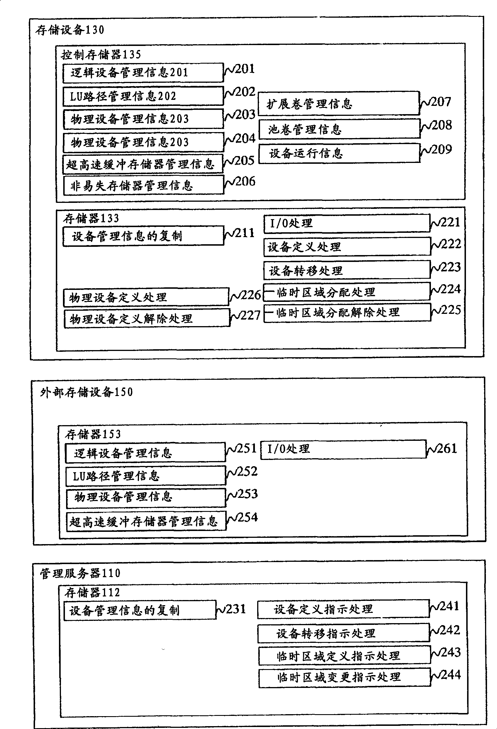
[0129] The software structure in the second embodiment is the same as that in the first embodiment figure 2 Indicated. In the second embodiment, first, corresponding to the allocation change process of the temporary area of ​​the nonvolatile memory 134, the tempora...


PUM


Abstract

The invention provides a storage system. The temporary area capacity required to be secured with respect to the whole permanent area is calculated in accordance with the capacity and access frequency of a host computer data permanent area of a disk device contained in the storage system and a disk device of an external storage device that is managed by a storage virtualization function of this storage system. The nonvolatile memory of this capacity is defined as the temporary area and is used to temporarily store host computer data when a data I/O from the host computer is processed. In addition, the required capacity of the temporary area of the nonvolatile memory is re-calculated in accordance with an event such as a configuration change where the external storage system is increased or reduced or the nonvolatile memory is increased or reduced and, if necessary, control is exercised to increase or reduce the capacity of the temporary area of the nonvolatile memory.

Description

technical field [0001] The present invention relates to a control method and a management method of a storage system accessed by a computer in a computer system, and more particularly to a method for allocating a storage area of ​​a nonvolatile memory mounted on the storage system and a method for managing the storage area. Background technique [0002] With the deregulation of the digitization of documents, the digitization of procedures, and the expansion of Internet commerce, the amount of information handled by companies and the like has exploded. In addition to such information growth, long-term records of corporate business activities (transaction information, emails, etc.) The increase in customer requirements for storage, etc. has led to a dramatic increase in the amount of data to be stored in storage devices, resulting in a large-scale storage system. [0003] Along with this, in the enterprise information system, on the one hand, the memory enhancement of each de...

Claims


Application Information

Patent Timeline
Patent Type & Authority Applications(China)
IPC IPC(8): G06F3/06
CPCG06F12/0246G06F3/0644G06F3/0626G06F3/0688G06F3/0631G06F3/068G06F3/067G06F3/0608G06F3/0656Y02D10/00
Inventor 山本康友
Owner HITACHI LTD
Why Eureka
Try Eureka