Efuse devices and efuse arrays thereof and efuse blowing methods

An electric fuse and array technology, which is applied in the field of electric fuse arrays with two-dimensional decoding, can solve the problems of the electric fuse array 10 occupying a large area and the like

Inactive Publication Date: 2009-02-11
MEDIATEK INC
View PDF0 Cites 13 Cited by
  • Summary
  • Abstract
  • Description
  • Claims
  • Application Information

AI Technical Summary

Problems solved by technology

Therefore, the electric fu...

Method used


Image

  • Efuse devices and efuse arrays thereof and efuse blowing methods
  • Efuse devices and efuse arrays thereof and efuse blowing methods
  • Efuse devices and efuse arrays thereof and efuse blowing methods

Examples


Embodiment Construction

[0013] In order to make the above-mentioned objects, features and advantages of the present invention more comprehensible, preferred embodiments are specifically cited below and described in detail in conjunction with the accompanying drawings.

[0014] The following description is a preferred contemplated mode of carrying out the invention. The purpose of these descriptions is to illustrate the general principles of the invention and should not be used to limit the invention. The scope of the present invention should be determined by the claims.

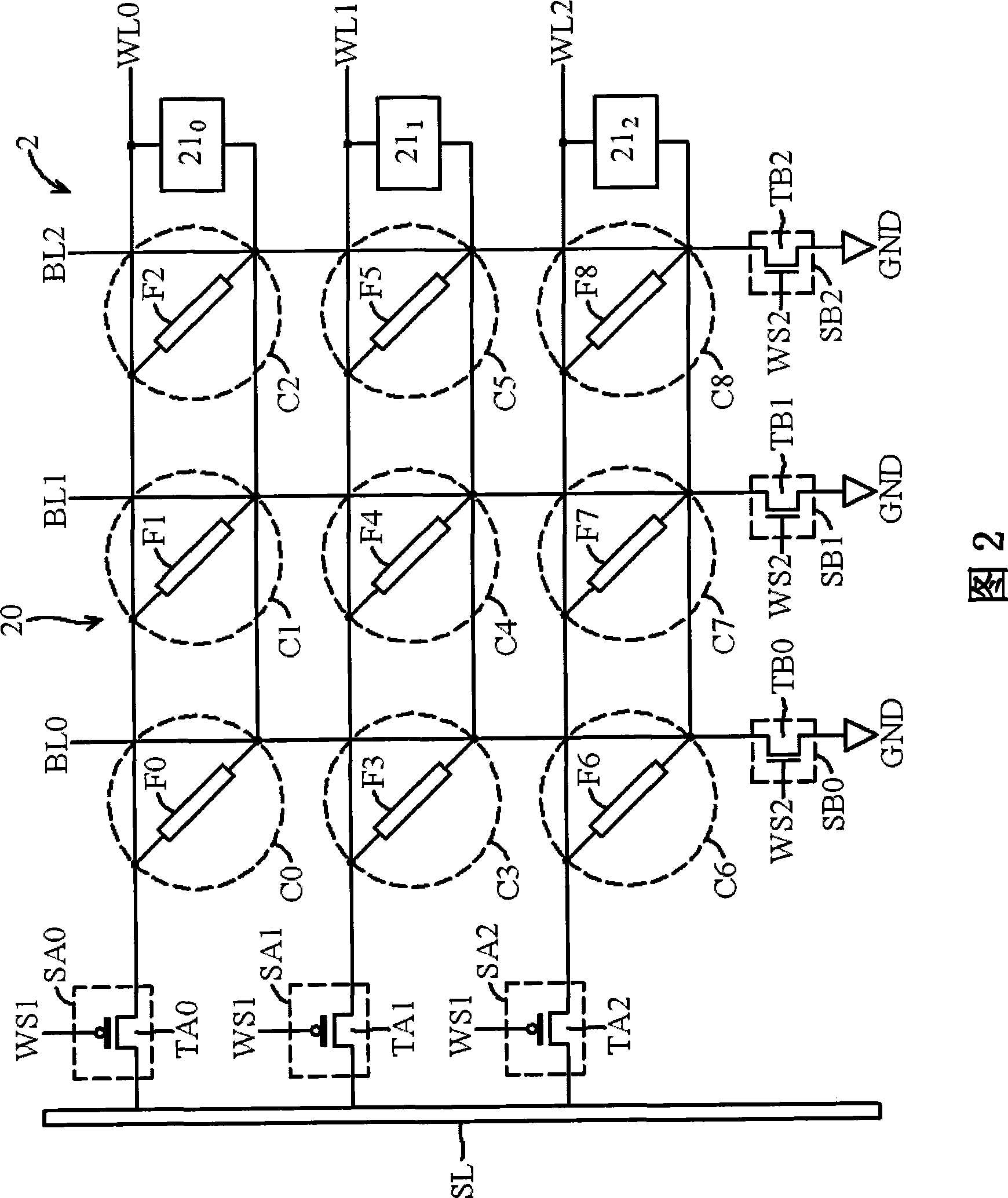
[0015] Figure 2 shows an exemplary embodiment of an efuse device according to the present invention. Referring to FIG. 2 , the electric fuse device 2 includes an electric fuse array 20 and a sensing circuit 21 . In this embodiment, the electric fuse array 20 is illustrated by taking a 3×3 array as an example. The electric fuse array 20 includes a plurality of word lines (word lines) WL0-WL2, a plurality of bit lines (bit lines) B...


PUM


Abstract

The invention provides an efuse array, an efuse device and an efuse blowing method. The efuse array comprises a plurality of word lines, at least one bit line, a plurality of cells, a plurality of first selection devices, and at least one second selection device. The word lines are interlaced with the bit line. The cells are disposed in an array, and each corresponds to one set of the interlaced word line and bit line. Each first selection device is coupled to one of the word lines, and the second selection device is coupled to the bit line. The invention is capable of reducing the sensing circuits needed for blowing the cells, and reducing the occupied area of the efuse array.

Description

technical field [0001] The present invention relates to an efuse device, and more particularly to an efuse array with two-dimensional decoding. Background technique [0002] Figure 1 shows a conventional electric fuse (efuse) array. Referring to FIG. 1 , a 4 x 2 electric fuse array 10 is taken as an example for illustration. The e-fuse array 10 includes a plurality of memory cells (ie, fuses 100-107) and blowing transistors T100-T107. Each of the fusing transistors T100-T107 is coupled between a memory cell and a reference voltage. When it is determined to burn the memory cell in the write mode, the corresponding fusing transistor is turned on, and the fusing current on the source line SL is supplied to the determined memory cell through the turned-on fusing transistor to fuse Burn this memory cell. For example, in the write mode, if it is decided to burn the memory cell 100, the fusing transistor T100 is turned on, and the fusing current on the source line SL is supplie...

Claims


Application Information

Patent Timeline
IPC IPC(8): G11C17/16
CPCG11C17/18G11C17/16
Inventor 黄睿夫
Owner MEDIATEK INC
Why Eureka
Try Eureka