Free angled driver and free angled hole abutment

A technology of drivers and implants, applied in the fields of dental implants, dental drilling, medical science, etc.

Inactive Publication Date: 2009-02-11
李钟琥
View PDF0 Cites 14 Cited by
  • Summary
  • Abstract
  • Description
  • Claims
  • Application Information

AI Technical Summary

Problems solved by technology

[0011] [11] Moreover, UCLA-type restorations have the same problems as retention screw-type

Method used


Image

  • Free angled driver and free angled hole abutment
  • Free angled driver and free angled hole abutment
  • Free angled driver and free angled hole abutment

Examples


Embodiment

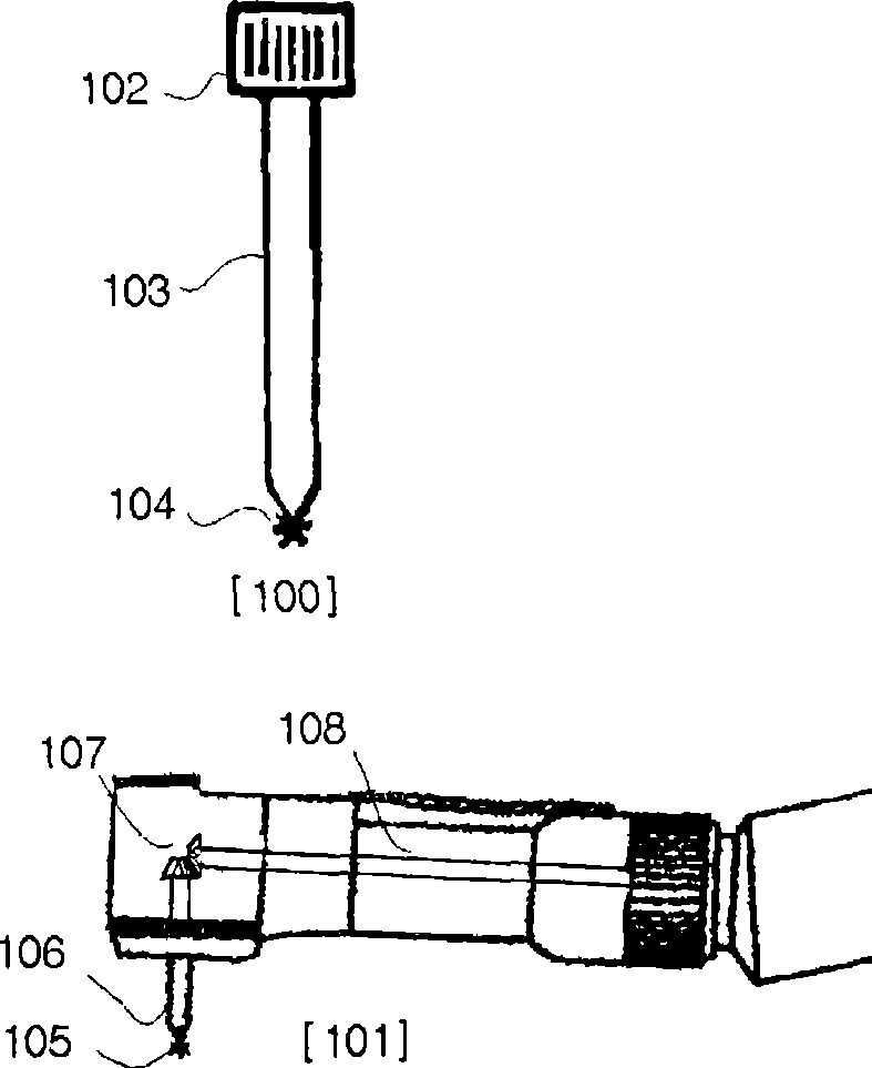
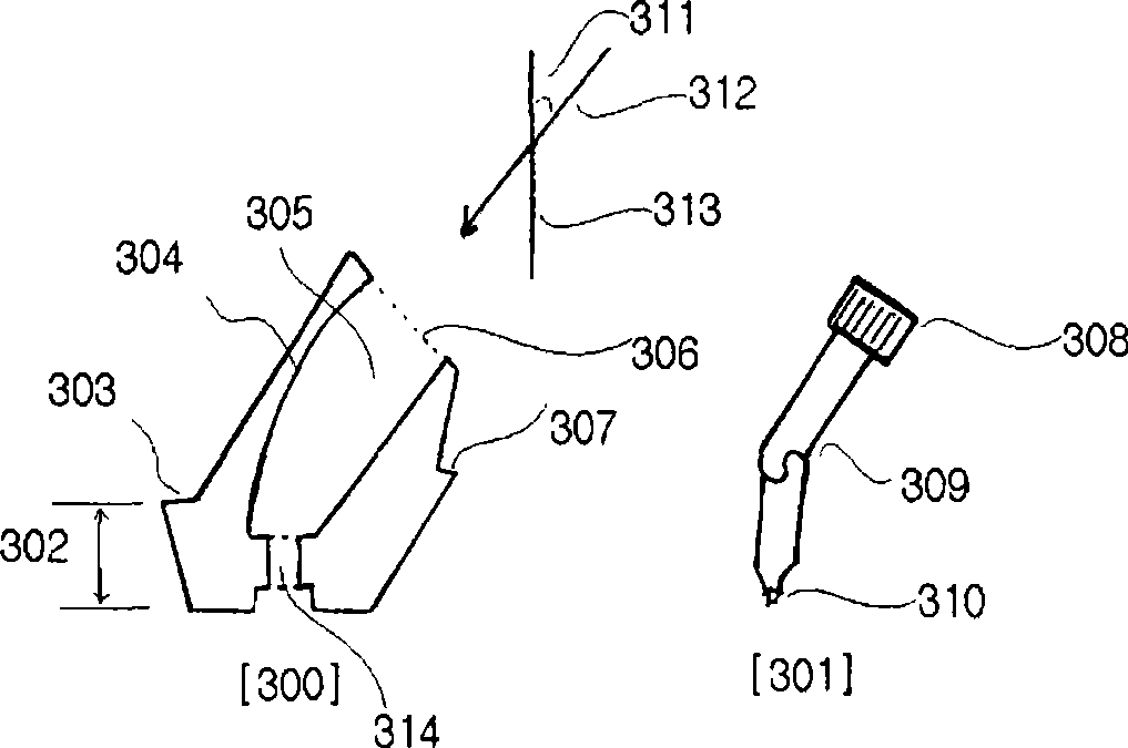
[0133] [128] The free-angle implant driver 301 for the implant is executed by the driver handle 308 of the power shaft 312 or the head type connection 1002, the torque transmission part 309 that transmits the rotational force from the driver handle along the driver rod 313, The working shaft 310 is made up of drive components.

[0134] [129] The torque transmitting member is a combination of rings, gears, wires or tubes.

[0135] [130] image 3 is a diagram of a free-angle driver with an annular angle portion 309. If the handle is turned, the ring transmits torque along the working end of the driver.

[0136] [131] Figure 5 is a view of a prosthesis 501 where the torque transfer parts of the two rings are made easy to tighten and loosen by a tube 509 guiding the retention screw holes.

[0137] [132] The free angle drive length from the working end 310 to the torque transfer member 309 should be short enough that these members should be located within the abutment.

[013...


PUM


Abstract

In case of straight driver, the entrance of screw inserting hole of implant prosthesis is on the same line with implant fixture's axis. Due to this position of the hole, final prosthesis has many difficulties. Thus. the free angled driver(301) is invented. For maxillay anterior teeth, we can move the screw hole to ligual surface of prosthesis(511). We can make esthetic and convenient prosthesis with capability of easy screwing and unscrewing. Also. I invented the free angled hole abutment(300) for the free angled implant driver,so we can move occlusal hole to the ideal position. It is an epoch-making change to solve many problems in the contemporary dental implant prosthetics.

Description

technical field [0001] [01] Dental implants have become an important part of modern dentistry. The dental implant consists of three parts, the implant fixture (implant fixture) 508, which is the implanted part in the bone, and the implant abutment (implantabutment) 506, which is connected to the implant implant by a retaining screw (screw). Connection; Tooth-shaped restoration, which is connected to the implant abutment. [0002] [02] In most cases, when the implant abutment is fixed to the implant implant, the abutment retaining screw 507 is screwed into the implant implant by a driver. In this case, the central axis of the driver body, the central axis of the implant abutment retaining screw, and the central axis of the implant implant are all in a straight line. At this stage, two types of drivers have been developed. One is a linear drive 100 and the other is a right angle drive system 101 . This right-angle drive system is used when the patient cannot open their mouth...

Claims


Application Information

Patent Timeline
Patent Type & Authority Applications(China)
IPC IPC(8): A61C8/00
CPCA61C8/0068A61C1/12A61C8/005A61C8/0089B25B17/00A61C8/00
Inventor 李钟琥
Owner 李钟琥
Why Eureka
Try Eureka