Bicycle crankset

A technology for bicycles and chainrings, used in bicycle frames, bicycle accessories, vehicle parts, etc., can solve problems such as bleeding, injury, scratching the crank, and achieve the effect of reducing distance, weight, and size.

Inactive Publication Date: 2009-02-11
米歇尔·加尼耶
View PDF7 Cites 4 Cited by
  • Summary
  • Abstract
  • Description
  • Claims
  • Application Information

AI Technical Summary

Problems solved by technology

Still, the distance is close to the length of the connecting arbor, so that the cyclist's ankle often scrapes against the crank during pedaling, causing injury and even bleeding

Method used


Image

  • Bicycle crankset
  • Bicycle crankset
  • Bicycle crankset

Examples


Embodiment Construction

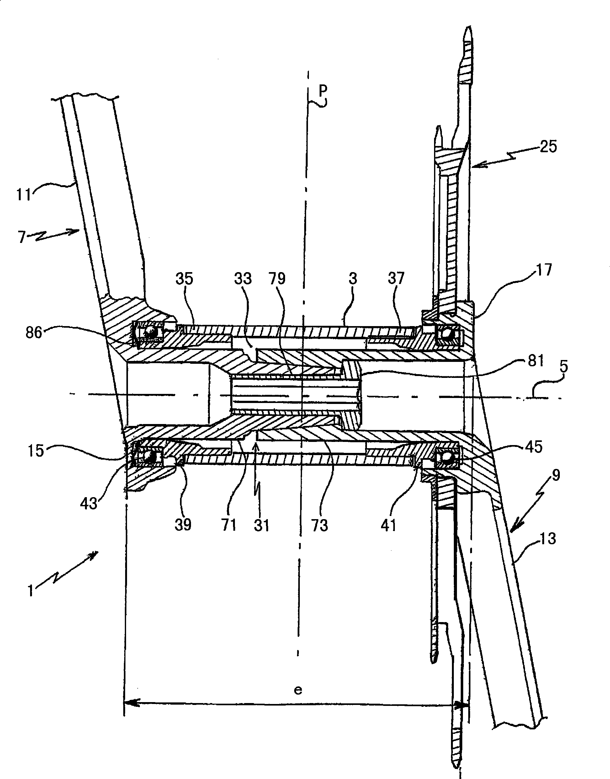
[0015] The bicycle chainring 1 which is the subject of the present invention may find application in particular of the type of racing bicycle or mountain bike, especially those intended for competition or intensive use. figure 1 The chainring 1 shown in is mounted on the frame 3 of the bicycle and is capable of rotating relative to the frame about an axis of rotation 5 which is perpendicular to the longitudinal plane "P" of the frame 3 of the bicycle and which, in normal use, when Said plane "P" coincides with the sagittal plane of the cyclist when he is in the riding position on the bicycle.

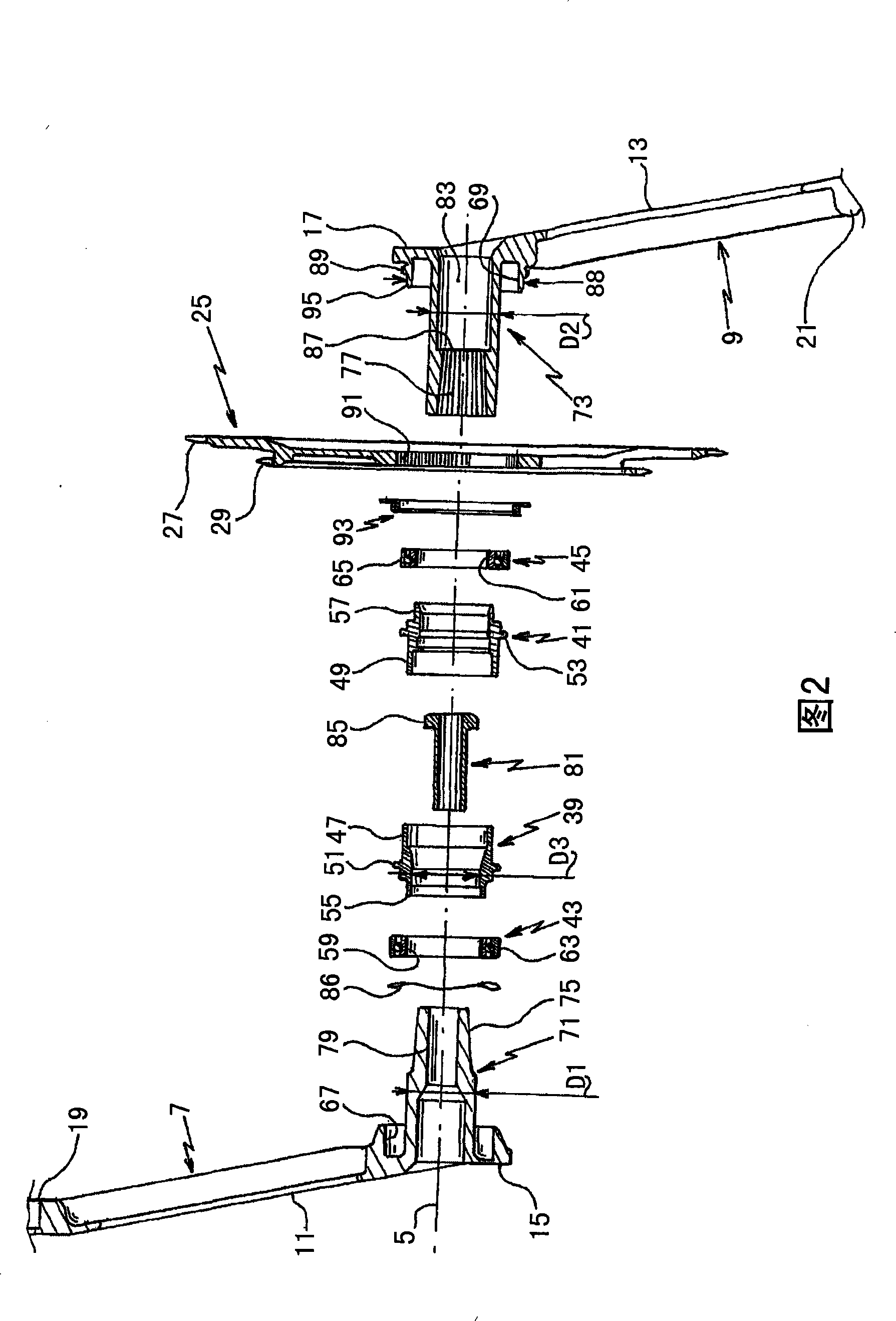
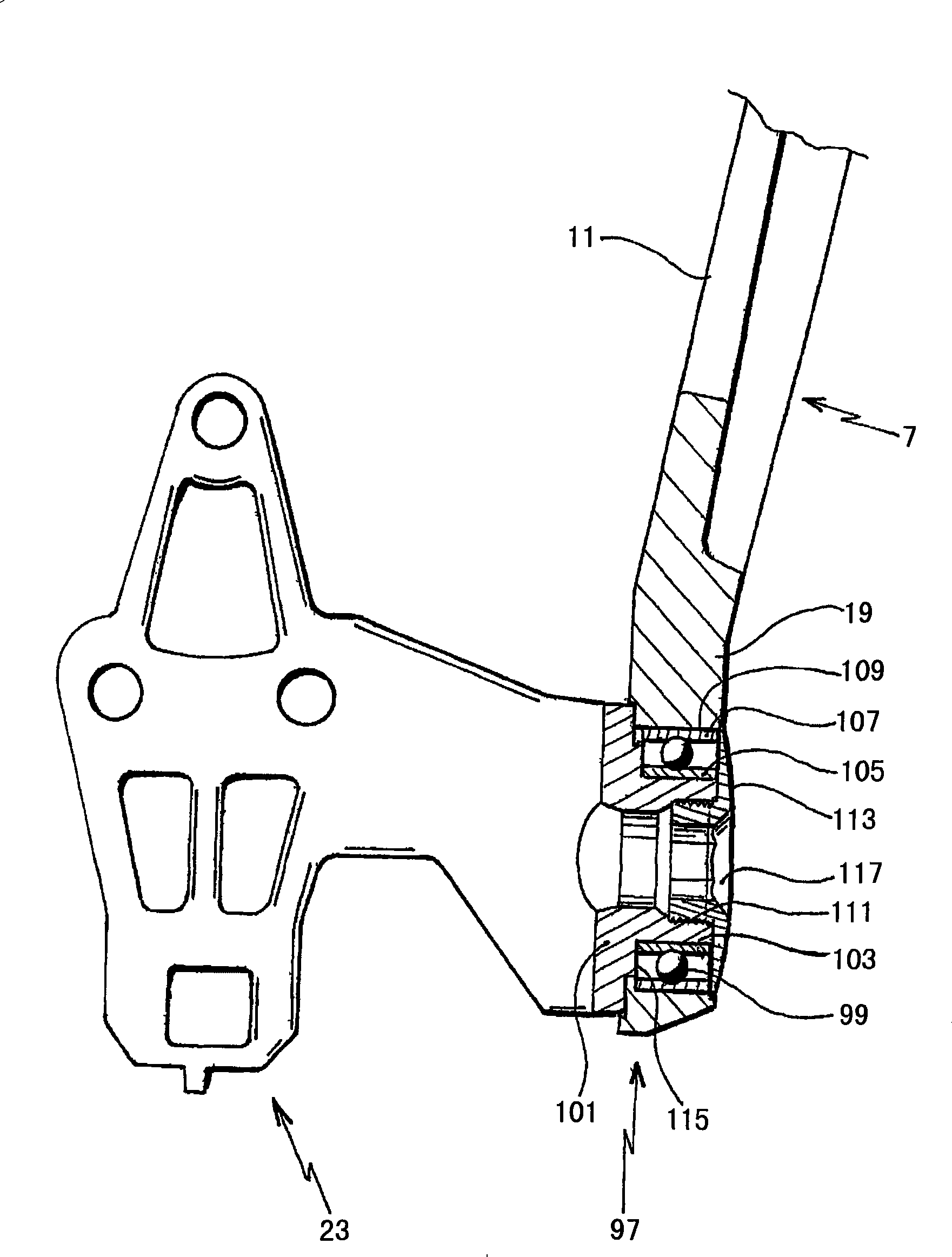
[0016] see figure 1 and Fig. 2, the chainring 1 comprises two cranks 7, 9, said cranks 7, 9 respectively comprising: a crank body 11, 13, which acts as a lever arm when the cyclist steps on the pedal; an axial end 15 , 17, which are arranged on the rotating shaft 5 of the chainring 1; and radial ends 19, 21, on which are connected pedals 23, such as image 3 shown in . In a preferred...


PUM


Abstract

A bicycle crankset (1) mounted on the frame (3) of the bicycle, two cranks (7, 9) and at least one chainring (25), the cranks being connected at their axial end (15, 17) by a connecting spindle (31). It is noteworthy in that the connection of the crankset to the frame is provided by means of assembling the axial ends to the frame, thus mechanically relieving the connecting spindle and reducing the dimensions of the connecting spindle and the distance ''e'' between the axial ends. The crankset is also noteworthy in that each crank takes a pedal which is fitted directly to the crank. This helps to reduce the weight of the crankset.

Description

technical field [0001] The present invention relates to a bicycle chainring that can be used, for example, in racing bicycles, mountain bikes, and even electric bicycles that require a chainring to start a motor. The invention will be especially suitable for use by manufacturers and bicycle dealers. Background technique [0002] The chainring is typically rotatably mounted to the bicycle frame and is subjected to the rotational motion caused by the pedaling of the rider. The rotational motion of this chainring drives one wheel of the bicycle, usually the rear wheel, through a chain or belt. [0003] The chainring partly comprises two cranks and at least one chainring rigidly connected to said cranks, the axial ends of the two cranks being connected to each other by means of a connecting spindle, said The arbor is commonly called the crankshaft and is housed in the housing of the bicycle frame; said cranks are arranged at 180° relative to each other and each have a pedal at...

Claims


Application Information

Patent Timeline
IPC IPC(8): B62K19/34B62M3/00
CPCB62M3/003
Inventor 米歇尔·加尼耶
Owner 米歇尔·加尼耶
Why Eureka
Try Eureka