Brake treadle apparatus of automobile and security protection method thereof

A technology of automobile braking and pedaling, which is applied in vehicle safety arrangements, foot-operated starting devices, pedestrian/passenger safety arrangements, etc., and can solve problems such as irreparable, damaged pedal devices, and driver injuries

Inactive Publication Date: 2009-02-18
CHERY AUTOMOBILE CO LTD
View PDF4 Cites 24 Cited by
  • Summary
  • Abstract
  • Description
  • Claims
  • Application Information

AI Technical Summary

Problems solved by technology

The defect of this patented technology is: it can only block the backward movement of the brake pedal, but cannot make it move toward the sheep to reduce the damage to the driver's feet and legs
The defect of this patented technology is that it depends entirely on the structure of the brake pedal to respond to the impact force, which is obviously more dangerous, because the driver may have been injured at this time.
[0010] The above-mentioned technical solutions all have the defect that the pedal device is seriously damaged and cannot be repaired when the protection is realized.

Method used


Image

  • Brake treadle apparatus of automobile and security protection method thereof
  • Brake treadle apparatus of automobile and security protection method thereof

Examples


Embodiment 1

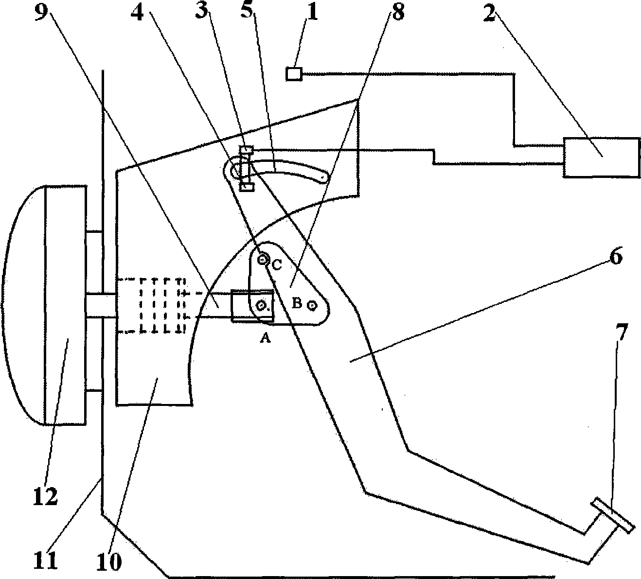
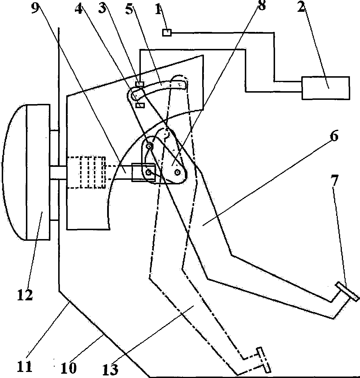
[0038] The end portion of the pedal arm 6 and the pedal bracket 10 cooperate with the structure as follows: on the side where the end portion of the pedal arm 6 is in contact with the pedal bracket 10, a pin shaft and the pedal arm 6 are fastened as one, and the pin shaft and the pedal shaft move The groove of guide rail 5 forms sliding fit, and the end dimension of bearing pin is greater than the width of pedal shaft motion guide rail 5 grooves. The way that the pin shaft is fixedly connected with the pedal arm 6 can be welding or riveting.

[0039] The pin shaft structure is adopted at the end position of the pedal arm 6, and the axis of the pin shaft is perpendicular to the pedal bracket 10, inserted into the groove of the pedal shaft movement guide rail 5, so that it can slide in the groove when it is released, Make the rotation of the pedal arm 6 move according to a certain trajectory.

[0040] The pin shaft can also be designed to rotate on the pedal arm 6, that is, the...

Embodiment 2

[0042] The setting method of the direction and position of the arc-shaped groove is as follows:

[0043] When the pedal shaft limiting device 4 locks the end of the pedal arm 6, that is, the fulcrum position, and the pedal arm 6 is in a state of no force, the pin shaft is in the groove of the pedal shaft movement guide rail 5 near the front of the vehicle body. At one end, the pedal 7 is at a position close to the driver, that is, at a limit position toward the rear of the vehicle. This setting method is suitable for the normal running state of the vehicle, and the driver can conveniently perform the operation of braking or accelerating (that is, releasing the brake). As long as the driver steps on the pedal 7, the pedal arm 6 will rotate with the pin shaft at the end of the groove of the pedal shaft movement guide rail 5 as the center of rotation. Vehicle braking.

[0044] When the pedal shaft limiting device 4 does not lock or releases the end of the pedal arm 6, that is, ...

Embodiment 4

[0046] A relay 3 is provided in the automobile brake pedal device, and the pedal shaft limiting device 5 locks or releases the position of the end of the pedal arm 6 , which is controlled by the trigger part of the relay 3 .

[0047] Its structure is generally: under the situation that the coil of relay 3 is not energized, the pin-shaped member made of the magnetic metal member in the pedal shaft limiting device 5 is inserted into the end of the pedal arm 6 to lock its position. After the relay wire is energized for 3 turns, the pin-shaped member is sucked out to make it lose its locking effect.

[0048] Or contrary to the above method, after the relay wire is energized for 3 turns, its magnetism is used to attract the metal member with magnetic induction to block the member at the end of the pedal arm 6 to realize the locking of its position. When the coil is de-energized, the metal member no longer plays a blocking role on the member at the end of the pedal arm 6. After the ...


PUM


Abstract

The invention belongs to the automobile structure technical filed and discloses an automobile brake pedal device. A pedal shaft movable lead rail (5) is arranged at the pinning pivot of a pedal frame (10) and the lead rail is of arc groove structure. The front end of a pedal arm (6) is fixed at one end of the pedal shaft movable lead rail (5) by a pedal shaft stop device (4). The arrangement of arc groove direction and position make a pedal (7) in a position closest to the driver when the pedal arm (6) gets no outer force, namely the limit position of the vehicle back direction. Adoption of the technical proposal makes use of vehicle front-collision sensor and pedal shaft stop and release control to perform control, which can protect the ankles and calves of driver actively. When front collision happens to a vehicle, the pedal moves forward and downward, and thus avoids and reduces the touch between the driver and the pedal. The device has the advantages of sensitive and rapid reaction, no damage to pedal and pedal arm, simple structure and reliable functions.

Description

technical field [0001] The invention belongs to the technical field of automobile structure, and relates to a structure for personal safety protection in an automobile operating mechanism. More specifically, the invention relates to an automobile brake pedal device. In addition, the invention also relates to a safety protection method for the pedal device. Background technique [0002] When a car is in a frontal collision, the driver usually presses down on the brake pedal quickly. Common brake pedal device, the brake pedal is rotatably connected to the pedal bracket fixed on the firewall. When the driver depresses the brake pedal, the push rod of the booster is pushed to make the brake master cylinder generate pressure to realize the braking action. [0003] Ordinary brake pedal devices can injure the driver's ankle or lower leg in a frontal collision. Because, when a frontal collision occurs, on the one hand, the distance between the driver and the pedal is shortened du...

Claims


Application Information

Patent Timeline
Patent Type & Authority Applications(China)
IPC IPC(8): B60T7/04B60R21/02
Inventor 张秀琴张亮
Owner CHERY AUTOMOBILE CO LTD
Why Eureka
Try Eureka