Backlight module and its light tube holder

A backlight module and lamp technology, which is applied in optics, light source fixing, nonlinear optics, etc., can solve the problems of cracking, collision, and difficulty in taking into account the convenience of the lamp 130 mounting and dismounting. The effect of increasing elastic force and gripping force

Active Publication Date: 2009-02-18
AU OPTRONICS CORP
View PDF0 Cites 7 Cited by
  • Summary
  • Abstract
  • Description
  • Claims
  • Application Information

AI Technical Summary

Problems solved by technology

When the clamping force of the lamp tube holder 150 is large, although the effect of clamping and fixing the lamp tube 130 is better, it is very difficult to insert or pull out the lamp tube 130 during the installation or disassembly of the lamp tube 130. Out of the light tube clip 150
Too much force is often used when installing or dismounting the lamp tube 130, which will easily cause the lamp tube 130 to break
On the other hand, when the clamping force of the lamp tube clamping seat 150 is small, the lamp tube 130 is easily detached from the lamp tube clamping seat 150, and then collides with nearby elements (such as the stopper 170) and breaks.
It can be seen from this that no matter whether the clamping force of the lamp tube holder 150 is large or small, it is difficult to balance the convenience of loading and unloading of the lamp tube 130 and the fixing effect of the lamp tube 130

Method used


Image

  • Backlight module and its light tube holder
  • Backlight module and its light tube holder
  • Backlight module and its light tube holder

Examples


Embodiment Construction

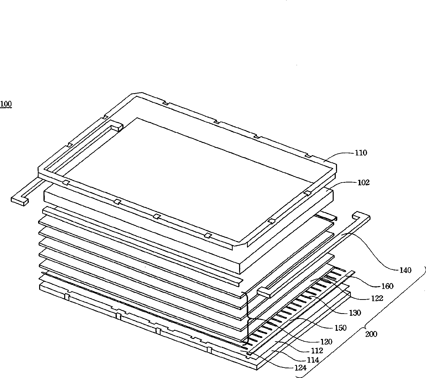
[0047] Please also refer to Figure 2A and Figure 2B, which are respectively a partially enlarged perspective exploded view and a combined schematic view of the backlight module 200 of the present invention. The backlight module 200 includes a backplane 114 , an optical film set 120 , a reflector 124 , a light tube 130 , an upper stopper 140 , a lower stopper 112 and a lamp holder 150 . They are explained one by one as follows.

[0048] The optical film set 120 includes multi-layer optical films, such as a diffuser 122, a light guide plate, a prism type enhancement film or a reflective polarization enhancement film, etc., which can be used to uniformly transmit the light emitted by the light source to the panel on the backlight module 200 . The reflection sheet 124 is used to reflect the light emitted by the light source into the optical film set 120 .

[0049] In a preferred embodiment, the light source is a lamp tube 130 , such as a tubular light-emitting element such a...


PUM


Abstract

The invention relates to a backlight module and the lamp tube clamp base thereof. The backlight module comprises a lamp tube, a lamp tube clamp base and an upper retaining piece. The lamp tube clamp base is provided with a pair of mutually-opposite clamping parts. The clamping parts are enclosed to form an opening; the two clamping parts are respectively positioned on both sides of the opening to clamp the lamp tube. A pair of elastic parts is respectively connected with the two clamping parts; the elastic parts extend upwards from the opening and are folded reversely to extend out of the opening and the two clamping parts. The elastic part extension distance is maintained between the two elastic parts. The lamp tube assembly-disassembly space and the lamp tube clamping front space are maintained between the clamping parts. Wherein, the position of the elastic part extension distance of the elastic parts is arranged between the position of the lamp tube assembly-disassembly space and the position of the lamp tube before-clamping space; thereby, the convenience of the assembly and disassembly of the lamp tube and the lamp tube fixation effect after mounting are guaranteed simultaneously.

Description

technical field [0001] The invention relates to a backlight module, and in particular to a lamp tube fixing device of the backlight module of a liquid crystal display. Background technique [0002] With the rapid progress of electronic technology and production technology of display devices (such as liquid crystal displays), the production cost of display devices is also decreasing day by day. Display devices are not only widely used in computer display devices, but are also widely used in the home life of ordinary consumers, such as watching TV programs and enjoying multimedia visual entertainment effects. [0003] Please refer to Figure 1A , which is a three-dimensional exploded view of a conventional display device. The display device 100 has a backlight module 200 and a display panel 102 . When the display panel 102 is a liquid crystal panel, since the liquid crystal itself does not emit light, the backlight module 200 is used to supply the light source, so that the d...

Claims


Application Information

Patent Timeline
Patent Type & Authority Applications(China)
IPC IPC(8): F21V19/00F21V21/00F21V23/06G02F1/13357G02F1/1335
Inventor 林文新林威宇
Owner AU OPTRONICS CORP
Why Eureka
Try Eureka