Radiating device

A technology of heat dissipation device and movable section, which is applied in the direction of cooling/ventilation/heating transformation, instrumentation, electrical digital data processing, etc. It can solve problems such as noise, reduce power consumption, reduce volume, and improve excessive noise Effect

Inactive Publication Date: 2009-02-18
INVENTEC CORP
View PDF0 Cites 42 Cited by
  • Summary
  • Abstract
  • Description
  • Claims
  • Application Information

AI Technical Summary

Problems solved by technology

The thin and light ultra-portable computer is equipped with a cooling fan, the noise generated by the fan will not be blocked too much, but can be directly transmitted to the outside of the device, causing a very serious noise problem

Method used


Image

  • Radiating device
  • Radiating device
  • Radiating device

Examples


Embodiment Construction

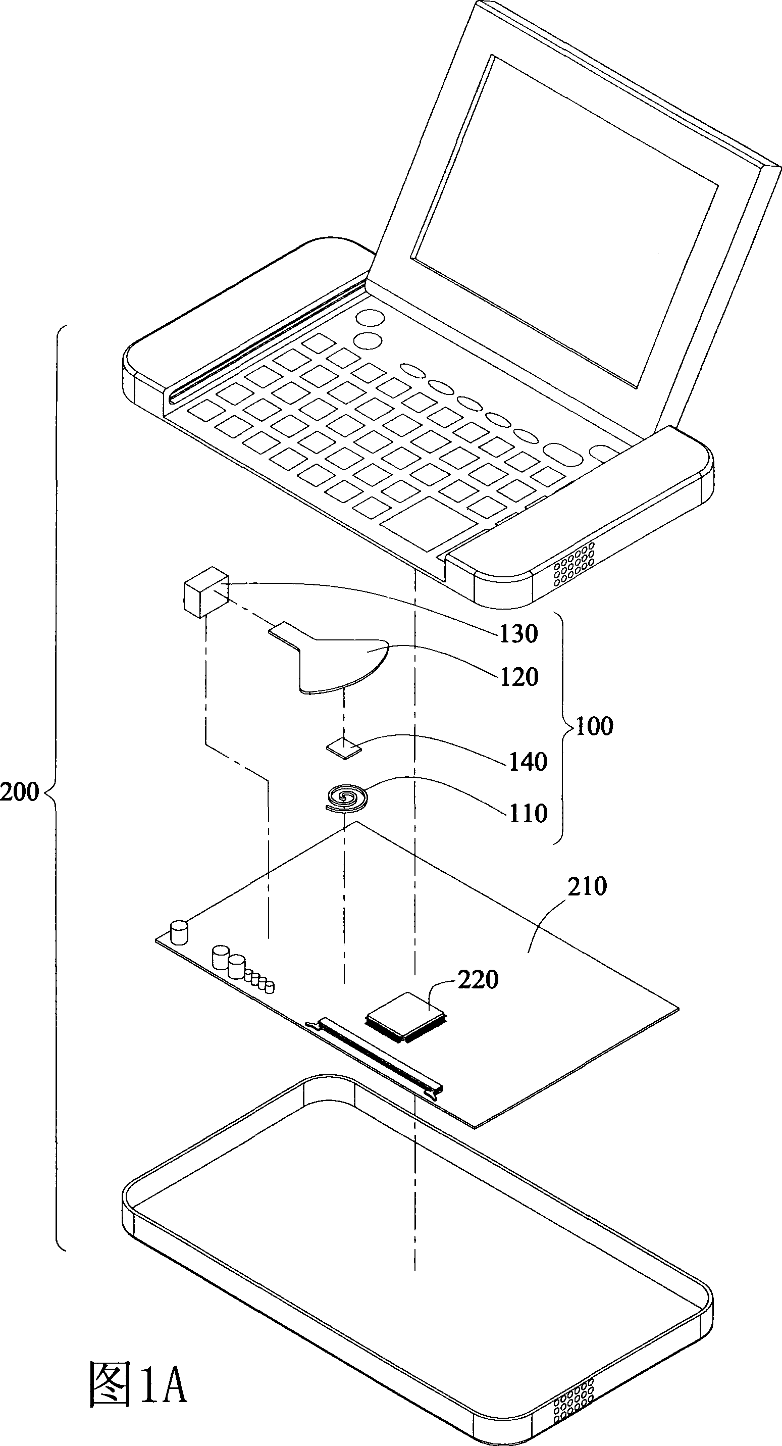
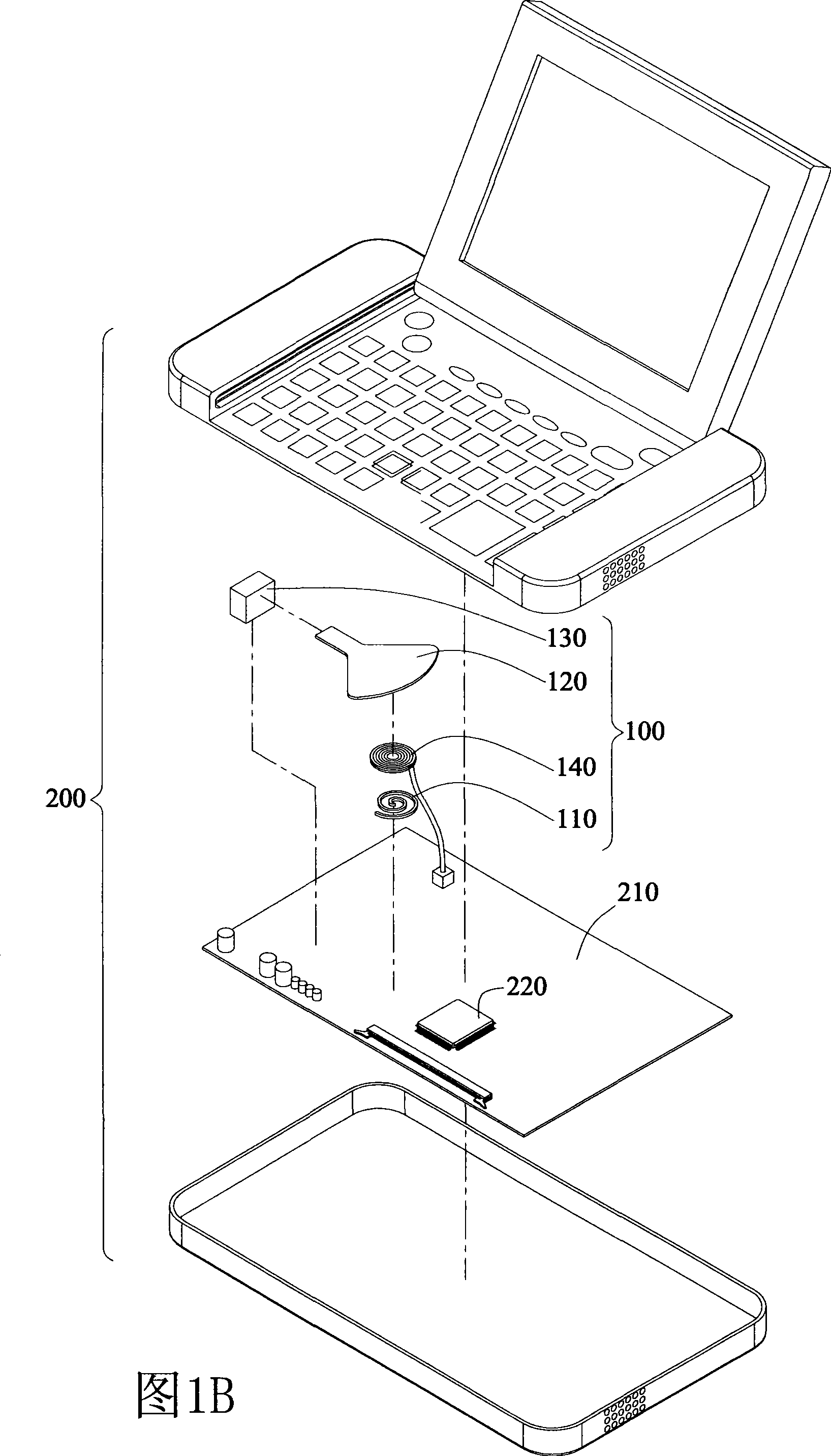
[0035] The heat dissipation device disclosed by the present invention is used for dissipating heat generated by electronic devices, such electronic devices include but not limited to portable electronic devices such as ultra-portable computers (UMPCs), personal computers, notebook computers, and PDAs. In the following detailed description of the present invention, an ultra-portable computer will be taken as the preferred embodiment of the present invention. However, the accompanying drawings are provided for reference and illustration only, and are not intended to limit the present invention.

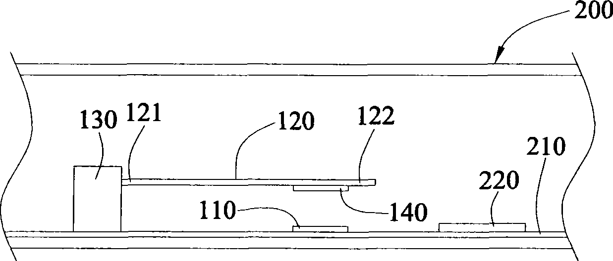
[0036] Please refer to the exploded diagrams of FIG. 1A and FIG. 1B . As shown in the figure, the heat dissipation device 100 of the first embodiment disclosed in the present invention is disposed in the electronic device 200 and receives a periodic power supply to dissipate heat energy generated by at least one heat generating component 220 on the circuit board 210 . Wherein the perio...


PUM


Abstract

The invention discloses a heat radiation device connecting with a periodic power supply for radiating for circuit board heating element. The radiation device possesses at least a coil, for receiving power supply and producing a magnetic field; and at least a swinging sheet, one end of which is fixed, and other end, suspended correspondingly to coil, wags driven by magnetic force of magnetic field to produce a air current.

Description

technical field [0001] The invention relates to a heat dissipation device, in particular to a heat dissipation device applied to portable electronic devices. Background technique [0002] With the current rapid development of electronic technology and consumers' increasing emphasis on the lightness and portability of consumer electronic products, today's electronic products, such as notebook computers, ultramobile personal computers (UMPC), PDA and other portable electronic products Devices have been gradually miniaturized. For users who need to go out frequently, portable electronic products have become easier to carry, greatly improving the convenience of use. [0003] Taking the ultra-portable computer as an example, due to the fast calculation speed of the electronic components inside the computer device, coupled with the small size of the electronic components, the heat generation per unit area increases accordingly. If the heat is not dissipated in time, the excessive ...

Claims


Application Information

Patent Timeline
Patent Type & Authority Applications(China)
IPC IPC(8): H05K7/20G06F1/20
Inventor 王少甫黄庭强沈诗珍许圣杰
Owner INVENTEC CORP
Why Eureka
Try Eureka