Wiring Member, Manufacturing Method of Wiring Member, and Wiring Member Connection Structure

a manufacturing method and wiring technology, applied in the direction of insulated conductors, flat/ribbon cables, cables, etc., can solve the problems of difficult to cover hard conductors, difficult to bend thick wires, etc., to reduce routing space, lighten and thin, and reduce manufacturing methods

Active Publication Date: 2018-06-21
YAZAKI CORP
View PDF26 Cites 18 Cited by
  • Summary
  • Abstract
  • Description
  • Claims
  • Application Information

AI Technical Summary

Benefits of technology

[0007]The present invention has been made in view of the above circumstances, and an object of the present invention is therefore to provide a wiring member that is lighter and thinner than conventional wires and can thus reduce a routing space, a manufacturing method of such a wiring member, and a connection structure for such a wiring member(s).

Problems solved by technology

However, it is difficult to bend a thick wire so that it conforms to the shape of a body panel.
Furthermore, it is difficult to cover a hard conductor such as a busbar that has been bent so as to be able to extend along a body panel, with an insulating covering by extrusion molding.

Method used


Image

  • Wiring Member, Manufacturing Method of Wiring Member, and Wiring Member Connection Structure
  • Wiring Member, Manufacturing Method of Wiring Member, and Wiring Member Connection Structure
  • Wiring Member, Manufacturing Method of Wiring Member, and Wiring Member Connection Structure

Examples


first embodiment

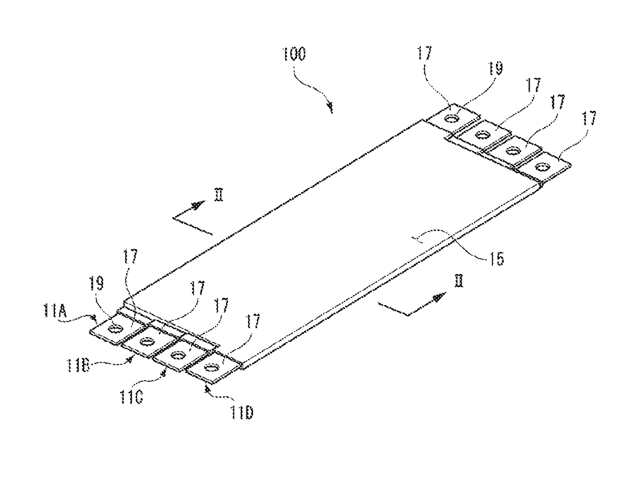
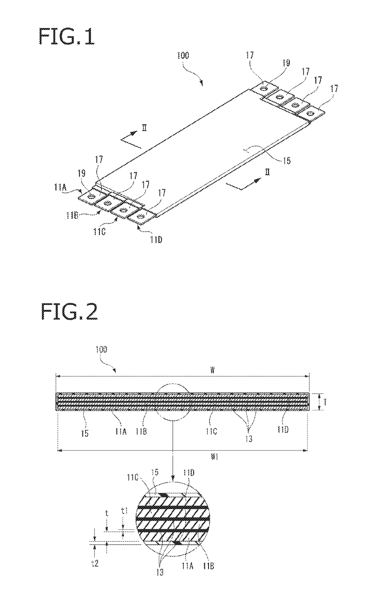
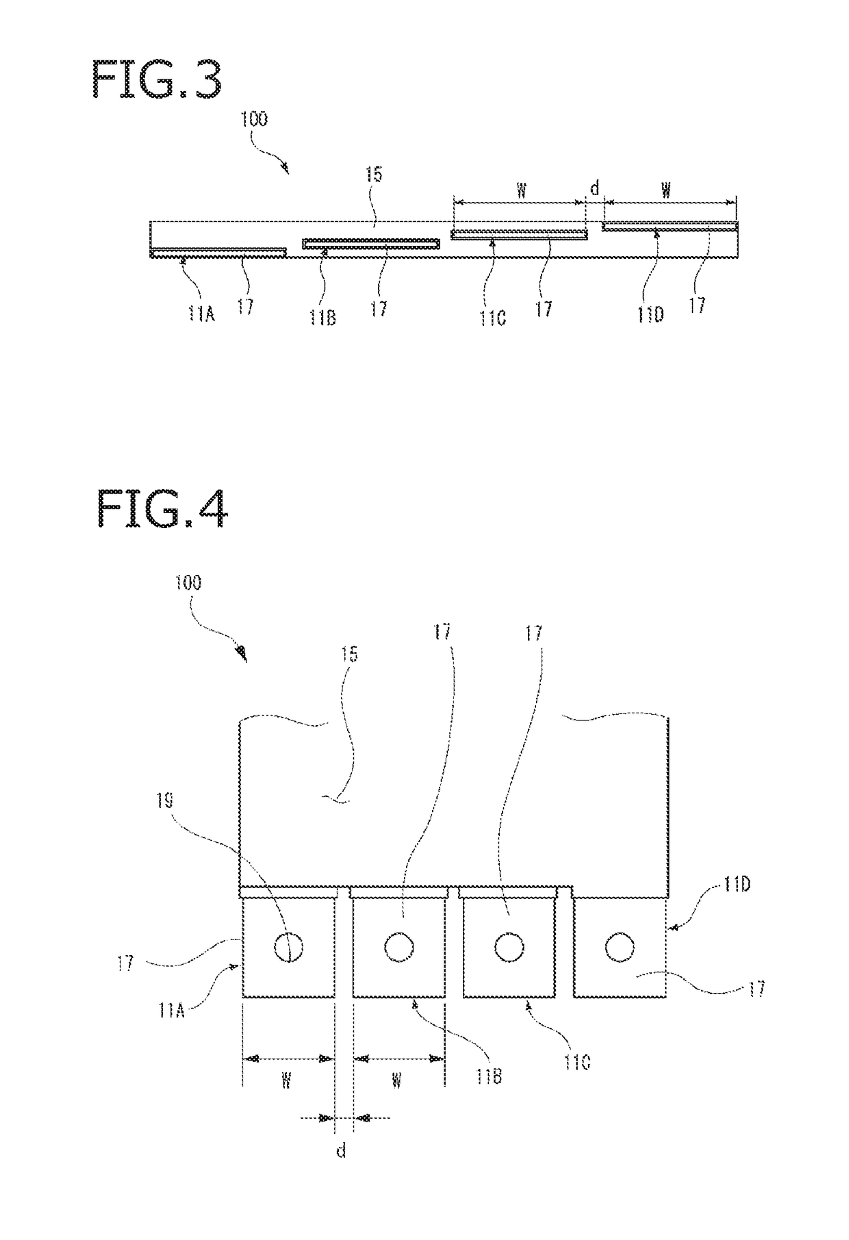
[0059]FIG. 1 is an overall perspective view of a vehicular wiring member 100 according to the invention. FIG. 2 is a sectional view, taken along arrowed line II-II in FIG. 1, of the vehicular wiring member 100.

[0060]The vehicular wiring member 100 according to the first embodiment of the invention is a wiring member including plurality of flat conductors 11A-11D (see FIG. 2), insulating sheet members 13, and an insulating layer 15.

[0061]The plural flat conductors 11A-11D employed in the first embodiment are laid on each other in the thickness direction and may be made of a conductive material such as a copper alloy or an aluminum alloy. This embodiment is directed to a case that they are flat conductors made of an aluminum alloy.

[0062]Each insulating sheet member 13 is interposed between adjacent ones of the flat conductors 11A-11D and electrically insulates them from each other. The insulating sheet members 13 may be a resin sheet member made of flexible PET (polyethylene terephtha...

second embodiment

[0072]FIG. 5 is a transverse sectional view of a vehicular wiring member 200 according to the invention. As shown in FIG. 5, the vehicular wiring member 200 is equipped with a shield layer 16 around plural flat conductors 11A-11D which are covered with an insulating layer 15. The shield layer 16 may be a braid or a foil. The outer surfaces of the shield layer 16 are covered with another insulating layer 15. In the vehicular wiring member 200 which is equipped with the shield layer 16, noise emission can be suppressed and influence of external noise can be avoided.

[0073]FIG. 6 is an overall perspective view of a vehicular wiring member 300 according to a third embodiment of the invention. The vehicular wiring member 300 according to the third embodiment is a wiring member produced by bending it so that it extends along, for example, a vehicle floor panel (body panel) 21 (see FIG. 8). In the vehicular wiring member 300, as described later, before formation of an insulating layer 15, p...

third embodiment

[0075]FIG. 7 is an overall perspective view of a vehicular wiring member 400 according to a modification of the invention. In the vehicular wiring member 400, as in the vehicular wiring member 300, before formation of an insulating layer 15, plural flat conductors 11A-11D which are laid on each other with flexible insulating sheet members 13 interposed between them are bent into a prescribed shape. The vehicular wiring member 400 is obtained by forming the insulating layer 15 around the thus-bent plural flat conductors 11A-11D.

[0076]The vehicular wiring member 400 is formed with plural bent portions 29, 31, 33, etc. so as to extend along the floor panel 21, and is also formed with plural convex bent portions 35 and 37 to stride respective cross members of the floor panel 21. In the vehicular wiring member 400, four long, flat conductors 11A-11D which are laid on each other with flexible insulating sheet members 13 interposed between them are covered with the insulating layer 15 by p...


PUM

PropertyMeasurementUnit
thicknessaaaaaaaaaa
voltagesaaaaaaaaaa
voltagesaaaaaaaaaa

Abstract

A wiring member includes a laminated flat conductor and an insulating layer provided around the laminated flat conductor. The laminated flat conductor includes a plurality of flat conductors laid on each other in a thickness direction of the laminated flat conductor, and insulating sheet members each of which is interposed between and electrically insulate adjacent ones of the plurality of flat conductors.

Description

CROSS REFERENCE TO RELATED APPLICATIONS[0001]This application is based on Japanese Patent Application (No. 2016-244781) filed on Dec. 16, 2016 and Japanese Patent Application (No. 2017-086562) filed on Apr. 25, 2017, the contents of which are incorporated herein by reference.BACKGROUND OF THE INVENTION1. Field of the Invention[0002]The present invention relates to a wiring member, a manufacturing method of a wiring member, and a wiring member connection structure.2. Description of the Related Art[0003]For example, vehicles with a rear battery require a long battery cable for transmitting electricity from the rear side to the front side. In general, circular or flat thick wires for automobiles are used as those battery cables. In many wire manufacturing methods of such thick wires, a conductor as a wiring member obtained by twisting copper element wires together is covered with an insulating covering (e.g., made of polyvinyl chloride) by extrusion molding. In the extrusion molding, h...

Claims


Application Information

Patent Timeline
Patent Type & Authority Applications(United States)
IPC IPC(8): H01B13/012H01B7/08H01B7/00H01R11/28B21D7/14B21C37/15
CPCH01B13/01254H01B7/08H01B7/0009H01R11/288B21D7/14B21C37/155B21D7/022H01R11/12H01B7/0823B60R16/0215
Inventor KOMINATO, YASUHIROKATO, SHINGOIIMURO, SHIGEKI
Owner YAZAKI CORP
Why Eureka
Try Eureka