Ultrasonic sound and sound wave detector based on triboelectricity nanometer generator

A nano-generator, triboelectric technology, applied in triboelectric generators, measuring ultrasonic/sonic/infrasonic waves, instruments, etc., can solve the problem of parasitic capacitance and distributed capacitance sensitivity and measurement accuracy, which are not suitable for low-intensity acoustic waves and high Ultrasonic detection of frequency, inability to detect ultrasonic signals in all directions, etc., to achieve the effect of being conducive to popularization and application, simplifying structure, simplifying structure and preparation process

Active Publication Date: 2014-05-07
BEIJING INST OF NANOENERGY & NANOSYST
View PDF6 Cites 18 Cited by
  • Summary
  • Abstract
  • Description
  • Claims
  • Application Information

AI Technical Summary

Problems solved by technology

The disadvantage is that the output is non-linear, parasitic capacitance and distributed capacitance have a greater impact on sensitivity and measurement accuracy, and the connection circuit is more complicated, etc., and the capacitor must be charged before use
[0003] The existing two underwater ultrasonic detectors have complex structures, and can only detect ultrasonic waves from a certain direction, but cannot detect ultrasonic signals from all directions. The most important thing is that they all need an external power supply to power or charge them.
Since the detector needs to work underwater for a long time, operations such as power supply or charging greatly limit its use range and reduce its use efficiency
Although some generators driven by piezoelectric and triboelectric properties have been developed, the structures of these generators are relatively complicated, and they are not suitable for efficient detection of low-intensity sound waves and high-frequency ultrasonic waves. Any kind of self-propelled sonic or ultrasonic detector is invented, which greatly affects the field of application of self-propelled generators

Method used


Image

  • Ultrasonic sound and sound wave detector based on triboelectricity nanometer generator
  • Ultrasonic sound and sound wave detector based on triboelectricity nanometer generator
  • Ultrasonic sound and sound wave detector based on triboelectricity nanometer generator

Examples


Embodiment 1

[0068] Example 1: Preparation of triboelectric nanogenerator

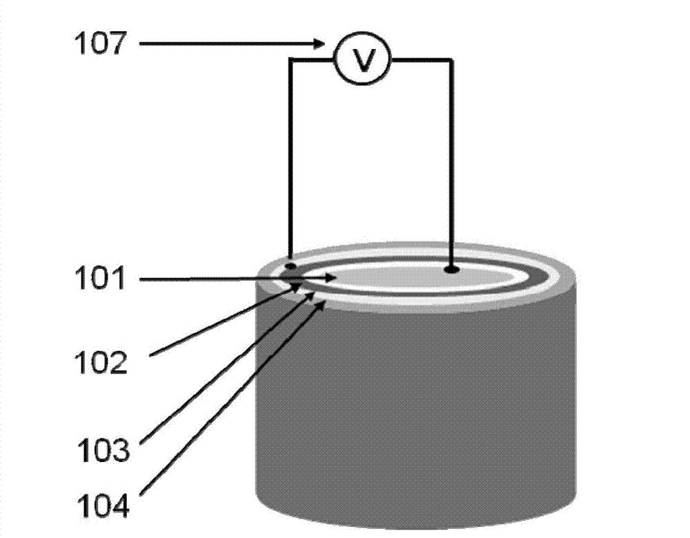
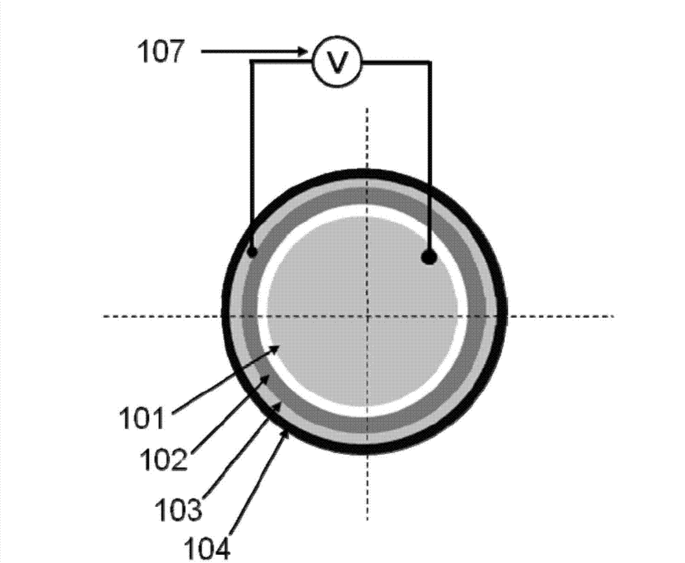
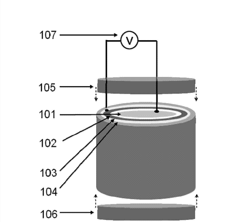
[0069] A layer of gold Au thin film is evenly plated on the lower surface of the polyimide with a length of 5 cm × width 6.5 cm × thickness 50 μm by evaporation method, and after cooling, one end of a wire is fixed on the outer side of the thin gold Au layer by welding. Realize the connection between the gold Au thin layer and the wire; on the surface of the gold Au thin film, evenly deposit a certain thickness of aluminum oxide as an insulating anti-corrosion layer by magnetron sputtering, so that the polyimide, Au thin film and aluminum oxide are formed. Flexible outer membrane made of thin layers of aluminum. An aluminum cylinder with a bottom diameter of 2cm and a height of 5cm is used as the conductive inner core, and one end of a wire is fixed on the top of the conductive inner core to realize the connection between the wire and the conductive inner core. Put the flexible outer film connected with the wires ...

Embodiment 2

[0071] Example 2: Preparation of triboelectric nanogenerator

[0072] A layer of indium tin oxide (ITO) film is evenly plated on the lower surface of polyimide with a length of 15cm × width 6.5cm × thickness 10μm by evaporation method, and after cooling, one end of a wire is fixed on the indium tin by welding. The outer side of the thin oxide layer is to realize the connection between the thin layer of indium tin oxide and the wire; on the surface of the indium tin oxide film, a certain thickness of aluminum oxide is evenly deposited by magnetron sputtering as an insulating anti-corrosion layer, thus forming a layer composed of Flexible outer membrane composed of polyimide, indium tin oxide thin film and aluminum oxide thin layer. A glassy carbon rod with a bottom diameter of 2 cm and a height of 15 cm is used as the conductive inner core, and one end of a wire is fixed on the top of the conductive inner core to realize the connection between the wire and the conductive inner ...

Embodiment 3

[0074] Embodiment 3: the preparation of ultrasonic detector

[0075] The lower surface of the poly(p-dimethylsiloxane) with a size of 10 cm x 12.8 cm x 100 μm is evenly coated with a layer of aluminum Al film by evaporation method, and after cooling, one end of a wire is fixed on the aluminum by welding. The outer side of the Al thin layer realizes the connection between the aluminum Al thin layer and the wire; on the surface of the aluminum Al thin film, a certain thickness of aluminum oxide is evenly deposited by magnetron sputtering as an insulating anti-corrosion layer, thus forming a polyimide, A flexible outer membrane composed of aluminum Al thin film and aluminum oxide thin layer. A copper cylinder with a bottom diameter of 2 cm and a height of 10 cm is used as the conductive inner core, and one end of a wire is fixed on the top of the conductive inner core to realize the connection between the wire and the conductive inner core. Put the flexible outer film connected ...


PUM


Abstract

This invention constructs a triboelectricity nanometer generator by utilizing a fact that polymeric materials and metal materials have various triboelectricity properties and prepares a detector with functions of detecting the ultrasonic sound and sound wave based on the nanometer generator. When the sound wave or the ultrasonic sound is transmitted to a flexible outer membrane of the detector, the flexible outer membrane or some parts of the flexible outer membrane produce corresponding mechanical vibration to enable the contact state between the flexible outer membrane and a conducting inner core to change correspondingly to drive the nanometer generator to output signals. The ultrasonic sound and sound wave detector can detect the ultrasonic sound or sound wave signals coming from various directions without power supply or charging in advance and utilizes the ultrasonic sound or the wave sound to produce mechanical vibration to realize self-driving. The light and thin flexible outer membrane is adopted, which simplifies the structure of the detector when the detection accuracy is improved, and the ultrasonic sound and sound wave detector has advantages of easy carrying, simple structure, easy usage and saving resources.

Description

technical field [0001] The invention relates to a self-driven ultrasonic and sound wave detector based on a triboelectric nanogenerator. Background technique [0002] So far, ultrasound is the only energy form that can be transmitted over a long distance in the deep sea, and the current practical technology for detecting underwater targets is only sonar technology. The receiving transducer is the core device in sonar, which converts underwater ultrasonic signals into electrical signals. According to the principle of energy conversion, there are two types of energy converters: piezoelectric and capacitive. Piezoelectric receiving transducers are sensors based on the piezoelectric effect. Its sensitive element is made of piezoelectric material, and the surface of piezoelectric material generates electric charge after being stressed. After the charge passes through the charge amplifier, the measuring circuit and the transformation impedance, it becomes the electric output pr...

Claims


Application Information

Patent Timeline
Patent Type & Authority Applications(China)
IPC IPC(8): H02N1/04G01H11/06
Inventor 王中林张虎林杨亚
Owner BEIJING INST OF NANOENERGY & NANOSYST
Why Eureka
Try Eureka