Planar illumination device

一种照明装置、面状的技术,应用在照明装置、照明装置的零部件、照明和加热设备等方向,能够解决大型化受限、增加导光板厚度等问题

Inactive Publication Date: 2009-02-18
FUJIFILM CORP
View PDF8 Cites 15 Cited by
  • Summary
  • Abstract
  • Description
  • Claims
  • Application Information

AI Technical Summary

Problems solved by technology

[0015] However, in the planar lighting devices using the light guide plate described in JP-A-07-36037, JP-A-08-248233, JP-08-271739, and JP-11-153963, in order to increase the size of To make the light reach a farther position from the light source, it is necessary to increase the thickness of the light guide plate itself
That is, there is a problem that the thickness and weight of the planar lighting device cannot be reduced.
[0016] Moreover, since JP-A-07-36037, JP-08-248233, JP-08-271739, and JP-11-153963 disclose that the thickness decreases as the distance from the incident position of the light source There is a limit to the reaching distance of light in the inclined shape or flat plate shape, so there is still a problem of limited size

Method used


Image

  • Planar illumination device
  • Planar illumination device
  • Planar illumination device

Examples


Embodiment Construction

[0071] A liquid crystal display device including the planar lighting device of the present invention will be described in detail based on the embodiments shown in the drawings.

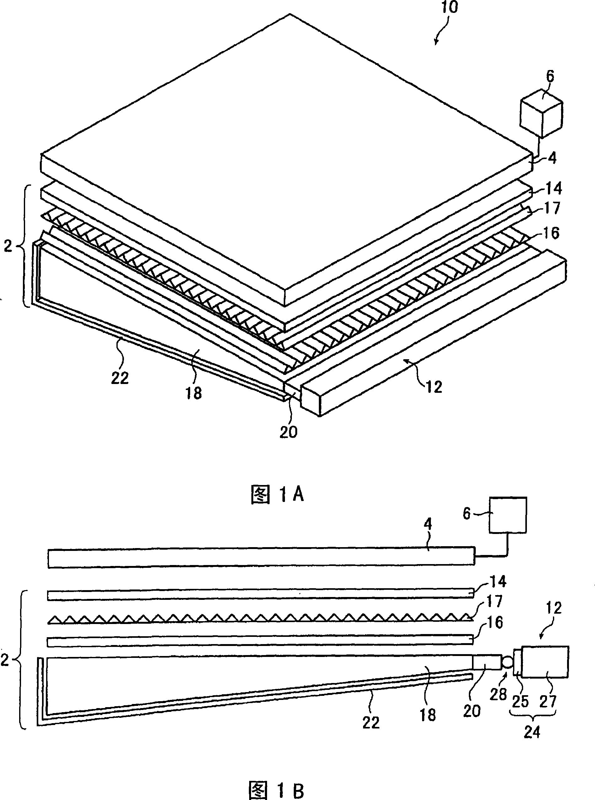
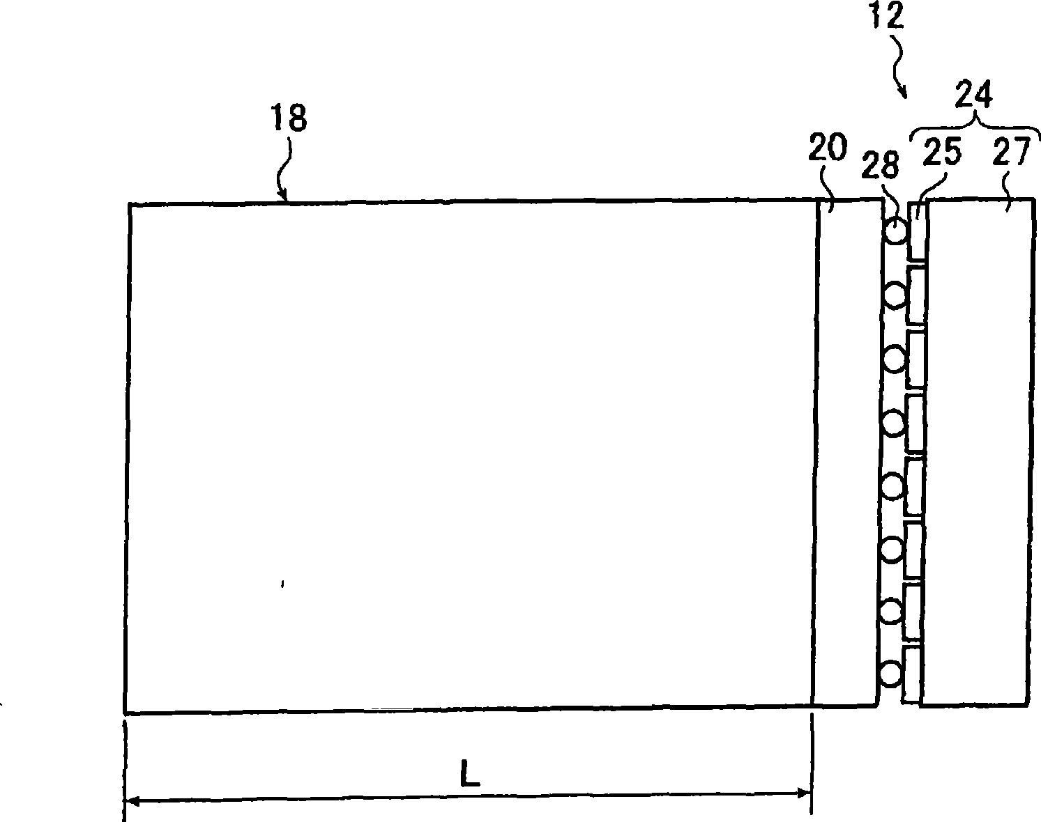
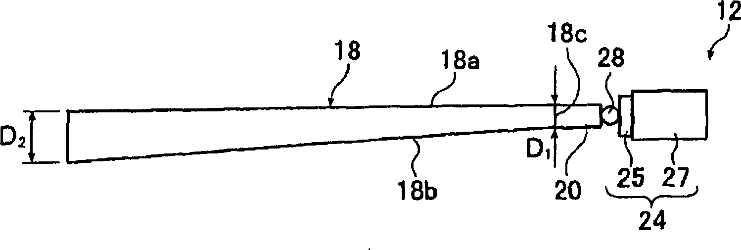
[0072] 1A is a perspective view schematically showing a liquid crystal display device including a planar lighting device according to a first embodiment of the present invention, and FIG. 1B is a schematic cross-sectional view of the liquid crystal display device. and Figure 2A It is a schematic plan view of a light guide plate and a light source used in a planar lighting device (hereinafter referred to as a backlight unit) of the present invention, Figure 2B It is a schematic cross-sectional view of the light guide plate.

[0073] The liquid crystal display device 10 includes a backlight unit 2 , a liquid crystal display panel 4 disposed on the light emitting surface side of the backlight unit 2 , and a drive unit 6 for driving the liquid crystal display panel 4 .

[0074] The liquid crystal displ...


PUM

PropertyMeasurementUnit
illuminanceaaaaaaaaaa
roughnessaaaaaaaaaa
sizeaaaaaaaaaa

Abstract

A planar illumination device that is thin and lightweight, can emit illumination light uniform and having no irregularity in brightness, and can be increased in size. The planar illumination device has a light source and at least one light guide plate placed facing the light source. The light guide plate has a light entrance surface facing the light source and a light exit surface including one side of the light entrance surface. The light guide plate is shaped such that the farther from the light entrance surface, the greater the thickness of the plate in the direction normal to the light exit surface. The light guide plate contains scattering particles that scatter light entering from the entrance surface and propagating in the plate.

Description

technical field [0001] The present invention relates to a planar lighting device used in liquid crystal display devices and the like. Background technique [0002] In the liquid crystal display device, a backlight unit for illuminating the liquid crystal display panel by irradiating light from the back side of the liquid crystal display panel can be used. The backlight unit is composed of a light guide plate that diffuses light emitted from a light source for illumination to illuminate the liquid crystal display panel; and a prism plate or a diffuser plate that uniformizes the light emitted from the light guide plate. [0003] Currently, the mainstream of backlight units for large LCD TVs is a so-called direct-type type in which a light guide plate is arranged directly above a light source for illumination. In this method, a plurality of cold-cathode tubes as light sources are disposed on the back of the liquid crystal display panel, and the interior is used as a white refl...

Claims


Application Information

Patent Timeline
Patent Type & Authority Applications(China)
IPC IPC(8): F21V8/00G02F1/13357F21Y101/02G02F1/1335
CPCG02B6/0046G02B6/0085G02B6/0041G02B6/0073G02B6/0083G02B6/0068G02F2001/133342G02B6/0061G02B6/0078G02B6/0063G02F1/133342F21V7/09
Inventor 岩崎修
Owner FUJIFILM CORP
Why Eureka
Try Eureka