
Airbag cover injection mold

An injection mold and airbag technology, which is applied to household appliances, other household appliances, household components, etc., can solve the problems of reduced production efficiency, high labor costs, poor product quality, etc., and achieves high production efficiency, simple structure, and low cost. Effect

Active Publication Date: 2016-12-07
NINGBO FANGZHENG TOOL
View PDF8 Cites 5 Cited by
  • Summary
  • Abstract
  • Description
  • Claims
  • Application Information

AI Technical Summary

Problems solved by technology

[0002] Automobile airbag system (SRS for short) is an auxiliary safety system, which usually appears as an auxiliary safety device for seat belts, including airbags, storage devices for storing airbags, and airbag covers, among which the airbag cover is important. One of the parts, the airbag cover is usually completed by injection molding. After the injection mold is completed, its waste and plastic parts will be connected together. Scraps are cut off, which not only has high labor costs, but also reduces production efficiency; there is another method that after the injection molding mold of plastic parts is opened, the point gate between the waste and plastic parts is broken through the cavity plate, and the broken gate is broken. The plastic parts are pushed out by the pusher plate through the thimble, and fall into the collection box. A special ejection mechanism needs to be set up, and the structure is cumbersome. At the same time, it is injected through a sprue during injection molding, and the product quality is poor.

Method used


Image

  • Airbag cover injection mold
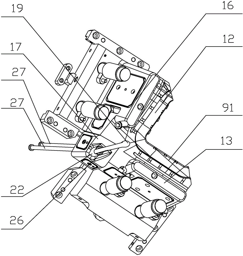
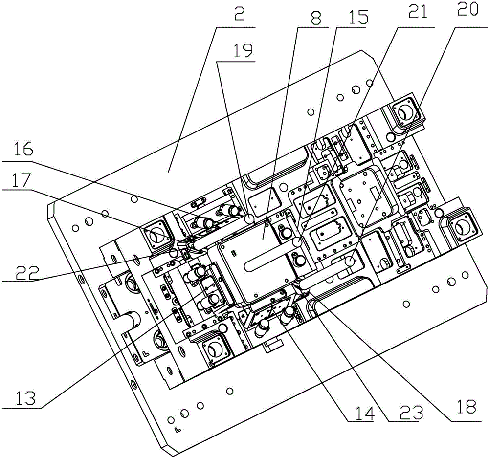
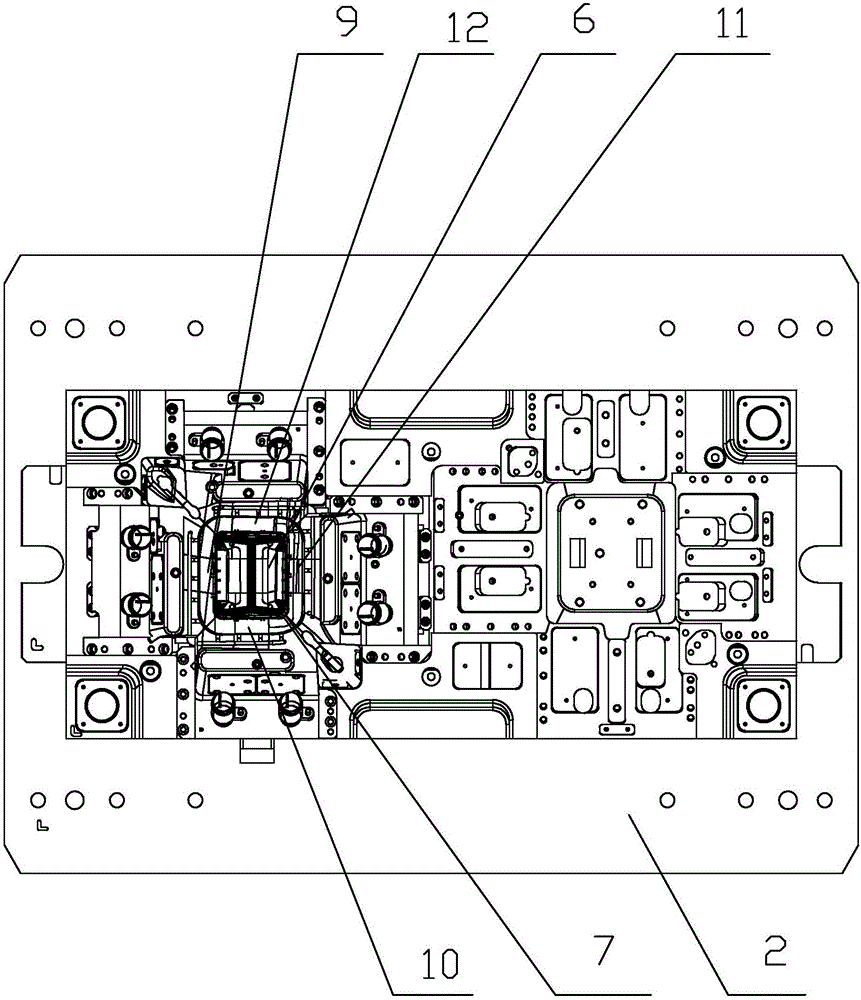
  • Airbag cover injection mold
  • Airbag cover injection mold

Examples


Embodiment Construction

[0021] The present invention will be further described below in conjunction with the accompanying drawings and specific embodiments.

[0022] As shown in the figure, the present invention provides an injection mold for an airbag cover, comprising an upper template 1, a lower template 2, a mold foot 3, a cover plate 4, a sprue and a product 6, and the lower template 2 is fixed on the mold foot 3 Above, the upper formwork 1 is located between the lower formwork 2 and the cover plate 4, the sprue is arranged on the cover plate 4, the lower surface of the upper formwork 1 is provided with an upper mold cavity 5, and the lower formwork 1 is provided with an upper mold cavity 5. The upper surface of the template 2 is provided with a lower mold cavity 7, and a mold cavity for forming the product 6 is provided between the upper mold cavity 5 and the lower mold cavity 7, and the upper mold cavity 5 for molding the product 6 is provided with a mold cavity. The upper mold core 8 on the s...


PUM

PropertyMeasurementUnit
depthaaaaaaaaaa

Abstract

The invention discloses an airbag cover injection mold. The airbag cover injection mold comprises an upper mold plate (1), a lower mold plate (2), a mold foot (3), a cover plate (4), a sprue (5) and a product (6). The lower mold plate (2) is fixed to the mold foot (3). The upper mold plate (1) is located between the lower mold plate (2) and the cover plate (4). The sprue (5) is arranged on the cover plate (4). An upper mold cavity (6) is arranged on the lower surface of the upper mold plate (1). A lower mold cavity (7) is arranged on the upper surface of the lower mold plate (2). A cavity used for forming the product (6) is arranged between the upper mold cavity (6) and the lower mold cavity (7). An upper mold core (8) used for forming the upper surface of the product (6) is arranged in the upper mold cavity (6). The airbag cover injection mold provided by the invention is low in cost, high in production efficiency and simple in structure, and the product quality is good.

Description

technical field [0001] The invention relates to the field of injection molds, in particular to an injection mold for an airbag cover. Background technique [0002] Automobile airbag system (SRS for short) is an auxiliary safety system, which usually appears as an auxiliary safety device for seat belts, including airbags, storage devices for storing airbags, and airbag covers, among which the airbag cover is important. One of the components, the airbag cover is usually completed by injection molding. After the injection mold is completed, the waste and plastic parts will be connected together. According to the existing technology, after the waste and plastic parts are demoulded at the same time, they will be manually put together. Scraps are cut off, which not only has high labor costs, but also reduces production efficiency; another is to break the point gate between the waste and plastic parts through the cavity plate after the injection molding mold of the plastic parts is...

Claims


Application Information

Patent Timeline
Patent Type & Authority Applications(China)
IPC IPC(8): B29C45/33B29C45/40B29C45/27B29C45/38B29L31/30
CPCB29C45/2708B29C45/33B29C45/38B29C45/4005B29C2045/2709B29L2031/3038
Inventor 刘扬叶军胡迪应华梁王一栋应可国
Owner NINGBO FANGZHENG TOOL
Learn More