
Light guide plate component and backlight device

A technology of light guide plate and backlight source, applied in the field of electronics, can solve the problem of not being able to enlarge the size of LCD TV

Inactive Publication Date: 2010-10-06
KONKA GROUP
View PDF0 Cites 5 Cited by
  • Summary
  • Abstract
  • Description
  • Claims
  • Application Information

AI Technical Summary

Problems solved by technology

[0004] The embodiment of the present invention provides a light guide plate assembly and a backlight device, which provides a solution to solve the problem that the size of the LCD TV cannot be enlarged in the prior art

Method used


Image

  • Light guide plate component and backlight device
  • Light guide plate component and backlight device
  • Light guide plate component and backlight device

Examples


Embodiment Construction

[0020] In order to make the objectives, technical solutions, and advantages of the present invention clearer, the embodiments of the present invention will be further described in detail below in conjunction with the accompanying drawings.

[0021] The embodiment of the present invention provides a light guide plate assembly and a backlight device. The light guide plate assembly is a side light guide plate assembly, and the backlight device is a side backlight device provided with the light guide plate assembly. The present invention The embodiments are generally applied to the field of liquid crystal televisions, of course, not limited to the field of liquid crystal televisions.

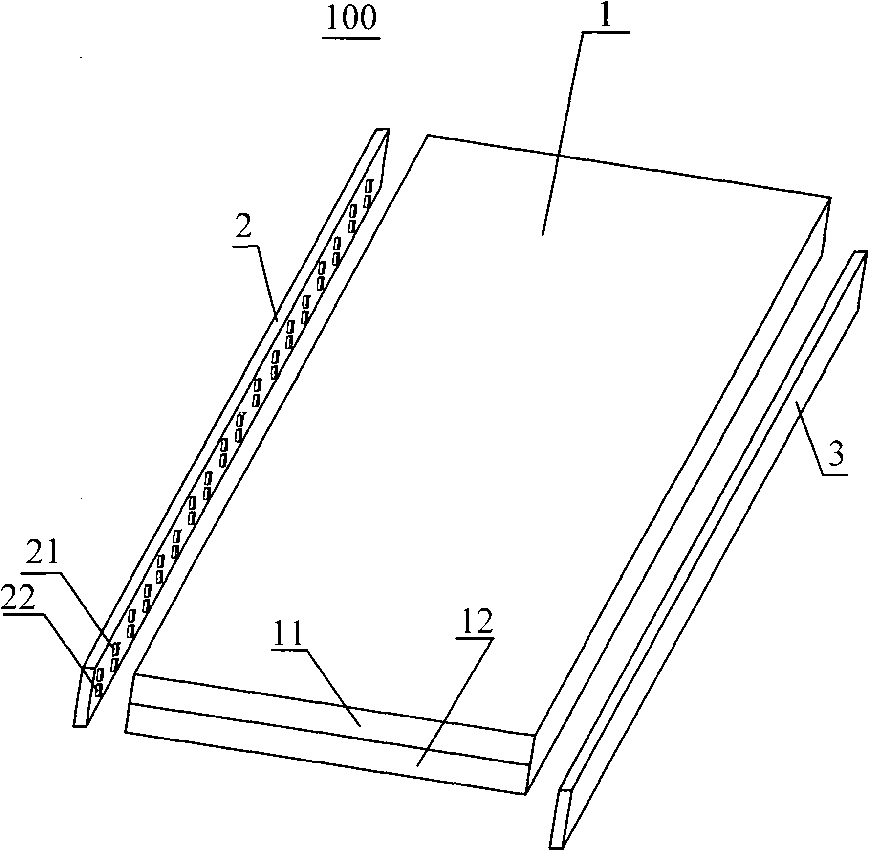
[0022] See figure 1 , Is a perspective view of a backlight device according to an embodiment of the present invention. In the embodiment of the present invention, figure 1 The light guide plate assembly 1, the light source group 2 and the light source group 3 are shown. The light guide plate assembly 1 in...


PUM


Abstract

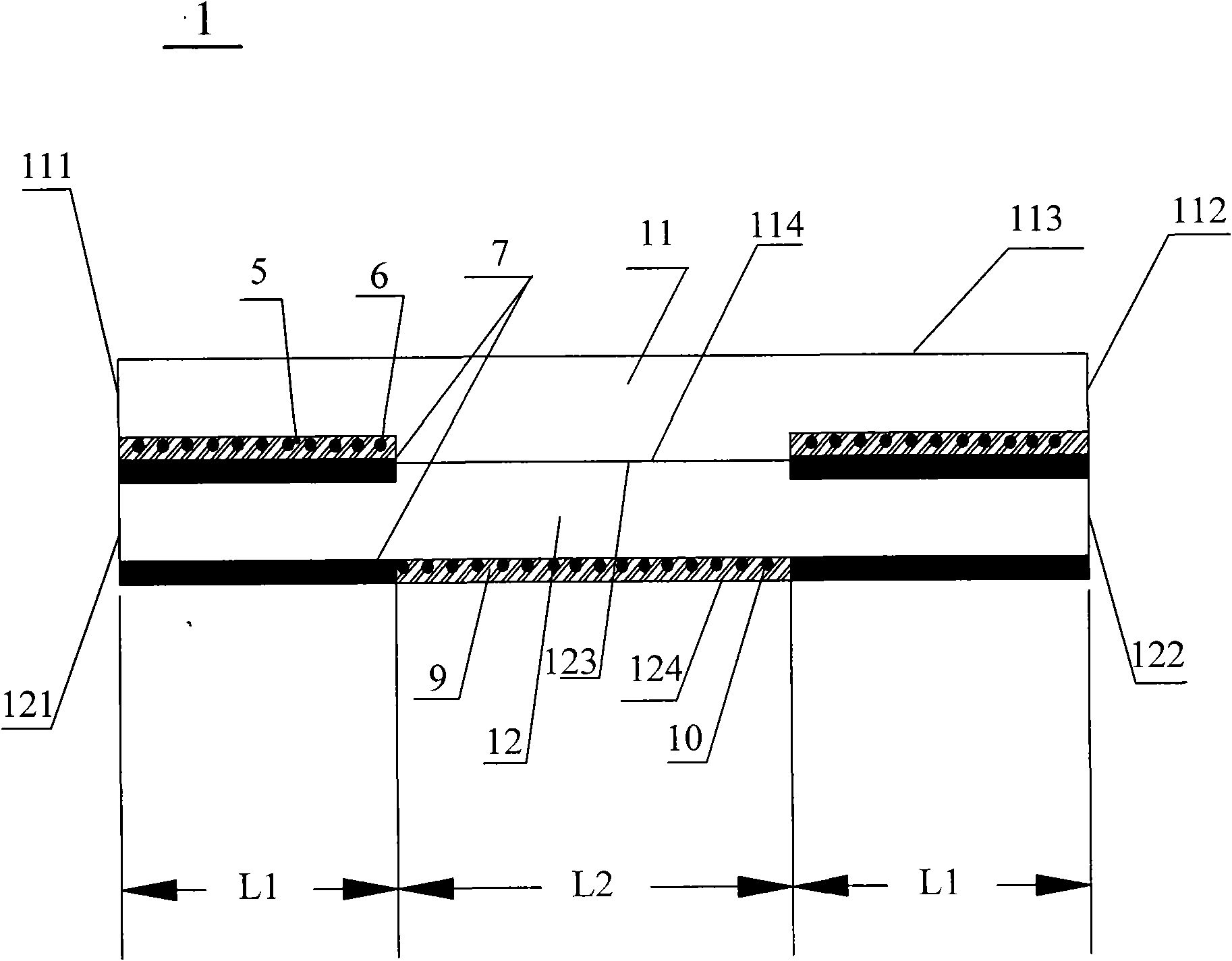
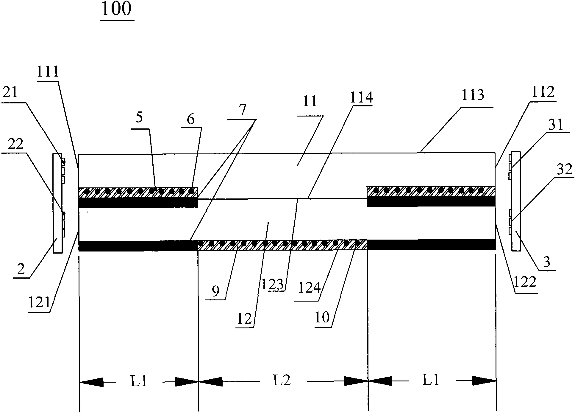
The invention provides a light guide plate component and a backlight device. The light guide plate component is spliced by two light guide plates, light sent by the light source of the first light guide plate is uniformly ejected by a screen dot and a reflecting film which are arranged on the area with stronger received light at the bottom surface of the first light guide plate irradiated by the light source; and a total reflecting film arranged on the light ejecting surface area of the second light guide plate corresponding to the area with stronger received light of the second light guide plate irradiated by the light source and the area with stronger received light at the bottom surface totally reflects the light sent by the light source of the second light guide plate to the area with weaker received light at the bottom surface of the second light guide plate irradiated by the light source, and the screen dot and the reflecting film which are arranged at the area with weaker received light at the bottom surface of the second light guide plate irradiated by the light source uniformly ejects the light at the area with weaker received light at the bottom surface of the second light guide plate irradiated by the light source so as to compensate the brightness of the middle area of the light ray ejected by the first light guide plate and meet the requirement of a large-size LCD TV on the backlight.

Description

Technical field [0001] The invention relates to the field of electronics, in particular to a side-lit liquid crystal TV light guide plate assembly and a backlight device. Background technique [0002] At present, side-backlit LCD TVs using light-emitting diodes LED (Light Emitting Diode) or cold cathode fluorescent tubes CCFL (Cold Cathode Fluorescent Lamp) are affected by the light source and block light guide plates, and the effective size is relatively difficult to increase. That said, it is difficult to achieve 30 inches. Some manufacturers design the light guide plate into a curved shape to increase the size of the LCD TV screen. [0003] In the process of implementing the present invention, the inventor found that in the prior art, designing the light guide plate into a curved shape or the like is not only difficult to process, but also expensive, which causes difficulties in the application of large-size side-lit TVs. Summary of the invention [0004] The embodiments of the ...

Claims


Application Information

Patent Timeline
Patent Type & Authority Applications(China)
IPC IPC(8): F21V8/00F21V13/02F21S8/00G02F1/13357F21Y103/00F21Y101/02
Inventor 马志凌郭斌
Owner KONKA GROUP
Learn More