Method for configuring transmitting-receiving channel of ultrasonic image-forming system

An ultrasonic imaging system and a technology of transmitting and receiving channels, applied in echo tomography, etc., can solve the problems of affecting image quality, low precision, and reducing the resolution of ultrasonic images, so as to improve image quality, reduce the number of channels, and take into account cost and reliability Effect

Inactive Publication Date: 2009-02-25
深圳蓝影医学科技股份有限公司
View PDF0 Cites 6 Cited by
  • Summary
  • Abstract
  • Description
  • Claims
  • Application Information

AI Technical Summary

Problems solved by technology

However, symmetrical folding is equivalent to analog addition, and the accuracy is lower than digital addition after AD conversion, so it will reduce the resolution of the ultrasound image and affect the image quality

Method used


Image

  • Method for configuring transmitting-receiving channel of ultrasonic image-forming system
  • Method for configuring transmitting-receiving channel of ultrasonic image-forming system
  • Method for configuring transmitting-receiving channel of ultrasonic image-forming system

Examples


Embodiment Construction

[0026] The present invention will be described in further detail below according to accompanying drawing and embodiment:

[0027] The core idea of ​​the technical scheme of the configuration method of the transceiver channel of the ultrasonic imaging system of the present invention is:

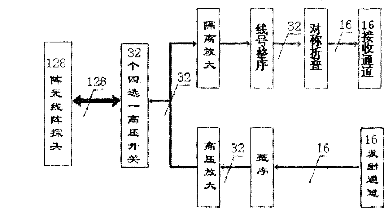
[0028] 1) Symmetrically fold the peripheral part of the transceiver channel, thereby reducing the number of digital processing channels, and maintaining the penetrating power of the image by adding peripheral signals.

[0029] 2) The middle part of the transceiver channel is directly sent to the digital processing channel, so as to preserve the details of the echo signal and improve the image resolution.

[0030] The specific technical scheme is: for the transceiver sub-array formed by adjacent array elements, set the number of array elements of the transceiver sub-array to be 2 to the nth power, n is a positive integer and n≧2, perform the following steps: There are no less than 2 array elem...


PUM


Abstract

The invention discloses a collocation method of a transceiving channel of an ultrasonic imaging system; for a transceiving sub-array composed of adjacent array elements, the number of the array elements of the transceiving sub-array is set to be n exponents of 2, and when n is a positive integral larger than or equal to 2, the following steps are conducted: each array element, which is positioned at the symmetrical and middle part of the transceiving sub-array and is not less than 2 and not more than n exponents of 2 minus 2 and is the integral multiple of 2, is correspondingly collocated with a receiving channel. The collocation method of the transceiving channel of the ultrasonic imaging system not only can maintain the detail of the images formed by ultrasonic echo signals and improve image quality, but also can reduce the number of channels, thus guaranteeing the image quality (resolution, penetrating power and intensity) and cost reliability at the same time.

Description

technical field [0001] The invention relates to the technical field of ultrasonic imaging, in particular to a method for configuring transceiver channels of an ultrasonic imaging system. Background technique [0002] Digital ultrasound imaging systems generally consist of figure 1 As shown in the module composition, under the action of the system control signal, the transmission drive unit generates a transmission drive signal, which forms a transmission high-voltage pulse after being driven by high voltage. This group of high-voltage pulses is sent to the corresponding probe array element through multiple T / R switches, generating Transmit ultrasonic waves with the required frequency, delay and intensity. The ultrasonic echo signal reflected by human tissue is received by the probe array element and converted into an echo electrical signal, and after pre-processing such as pre-amplification, time gain compensation (TGC), low-pass filtering, etc., it directly enters the high...

Claims


Application Information

Patent Timeline
Patent Type & Authority Applications(China)
IPC IPC(8): A61B8/14
Inventor 刘明宇
Owner 深圳蓝影医学科技股份有限公司
Why Eureka
Try Eureka