
Rotary type atomizing sprayer

An atomization spraying and rotary technology, applied in the direction of spray evaporation, hydrocarbon oil dehydration, etc., can solve the problems of difficult oil-water separation, accelerated wear and corrosion of equipment, and achieve the reduction of bonding rate, the improvement of atomization efficiency, and the increase of fog The effect of reducing the area

Inactive Publication Date: 2009-02-25
镇江市长江机电设备厂有限公司
View PDF0 Cites 4 Cited by
  • Summary
  • Abstract
  • Description
  • Claims
  • Application Information

AI Technical Summary

Problems solved by technology

[0002] When hydraulic oil, mechanical oil, cooling oil and other lubricating oils are used in the process of mechanical operation, moisture, gas, volatile substances and impurities will inevitably be mixed into the lubricating oil due to various reasons, thus causing accelerated wear of the equipment , rust and reduce service life, therefore, in order to solve the use effect of high-viscosity oil, it is necessary to purify the high-viscosity oil
The spray device in the vacuum atomization chamber is a cycle process of the oil purification device, which plays the role of making the medium from emulsification to atomization. Because the traditional oil purification equipment is that the medium is demulsified from the vacuum separation chamber and then enters the vacuum atomization state. In the chamber, the medium is atomized through the countless tiny pores of the spray head. Since there is no buffer or device in the spray device that is conducive to the atomization effect of the medium, the atomization effect is poor and it is difficult to create an oil-water separation. surroundings

Method used


Image

  • Rotary type atomizing sprayer

Examples


Embodiment Construction

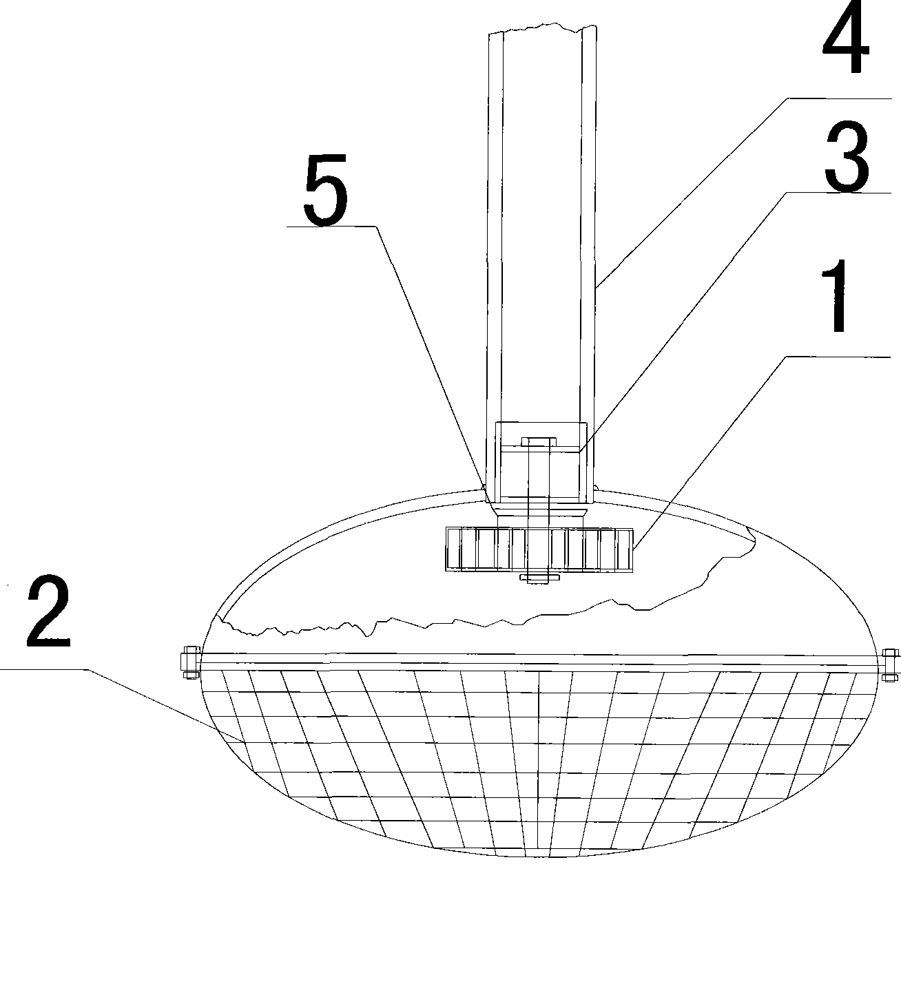
[0008] The rotary atomizing spray device of the present invention comprises a rotating impeller 1, a sprayer nozzle 2, an impeller fixing seat 3, an oil guide pipe 4, and an impeller guide cover 5; the outlet of the oil guide pipe 4 is provided with an impeller guide cover 5, The impeller fixing seat 3 is located in the impeller guide cover 5, the rotating impeller 1 is located under the impeller guide cover 5 and the impeller fixing seat 3, the rotating shaft of the rotating impeller 1 is located in the impeller fixing seat 3, and the spray hole 2 is located in the rotating impeller 1. below. The blades of the rotary impeller 1 have an inclination angle with the axial direction of the rotary impeller 1 .

[0009] The oil heated by the far-infrared heater enters the impeller guide cover 5 through the oil guide pipe 4, and the oil is directly introduced into the middle hole of the rotating impeller 1 by the impeller guide cover 5, and is emitted to the surroundings through the ...


PUM


Abstract

The present invention relates to a rotary atomizing spray device which is used in the part of the product of a high-viscidity oil cleaning device of large mechanical equipment, realizes the function of improving the atomization effect and belongs to the technical field of spray device manufacture. The device comprises a rotary impeller (1), a sprayer nozzle (2), an impeller fixing base (3), an oil guide pipe (4) and an impeller guide cover (5). An outlet of the oil guide pipe (4) is provided with the impeller guide cover (5). The impeller fixing base (3) is arranged in the impeller guide cover (5). The rotary impeller (1) is arranged under the impeller guide cover (5) and the impeller fixing base (3). The rotating shaft of the rotary impeller (1) is arranged in the impeller fixing base (3). The sprayer nozzle (2) is arranged under the rotary impeller (1). A vane of the rotary impeller (1) forms obliquity with the rotary impeller (1) along the axial direction.

Description

technical field [0001] The invention relates to a component used in a high-viscosity oil purification device for large-scale mechanical equipment, which can improve the atomization effect and belongs to the technical field of spraying device manufacture. Background technique [0002] When hydraulic oil, mechanical oil, cooling oil and other lubricating oils are used in the process of mechanical operation, water, gas, volatile substances and impurities will inevitably be mixed into the lubricating oil due to various reasons, which will cause accelerated wear of the equipment , rust and reduce service life, therefore, in order to solve the use effect of high-viscosity oil, it is necessary to purify the high-viscosity oil. The spray device in the vacuum atomization chamber is a cycle process of the oil purification device, which plays the role of making the medium from emulsification to atomization. Because the traditional oil purification equipment is that the medium is demuls...

Claims


Application Information

Patent Timeline
IPC IPC(8): B01D1/20C10G7/04
Inventor 张晓进
Owner 镇江市长江机电设备厂有限公司
Learn More