Base corner of rotary compressor

A rotary compressor and compressor technology, applied in the field of compressors, can solve the problems of waste of materials, waste of material support stress, etc., and achieve the effect of improving the die size and saving materials

Inactive Publication Date: 2009-02-25
LG ELECTRONICS (TIANJIN) APPLIANCES CO LTD
View PDF0 Cites 2 Cited by
  • Summary
  • Abstract
  • Description
  • Claims
  • Application Information

AI Technical Summary

Problems solved by technology

However, the support rib 21 of the prior art adopts a long piece structure with a whole body, and the bottom corner is made of metal material. When the compressor is not installed in the air conditioner, the stress of the support rib is relatively surplus, and the material is relatively wasteful; No stress, there is a waste of material and support stress

Method used


Image

  • Base corner of rotary compressor
  • Base corner of rotary compressor
  • Base corner of rotary compressor

Examples


Embodiment Construction

[0024] Below in conjunction with accompanying drawing and specific embodiment the present invention is described in further detail:

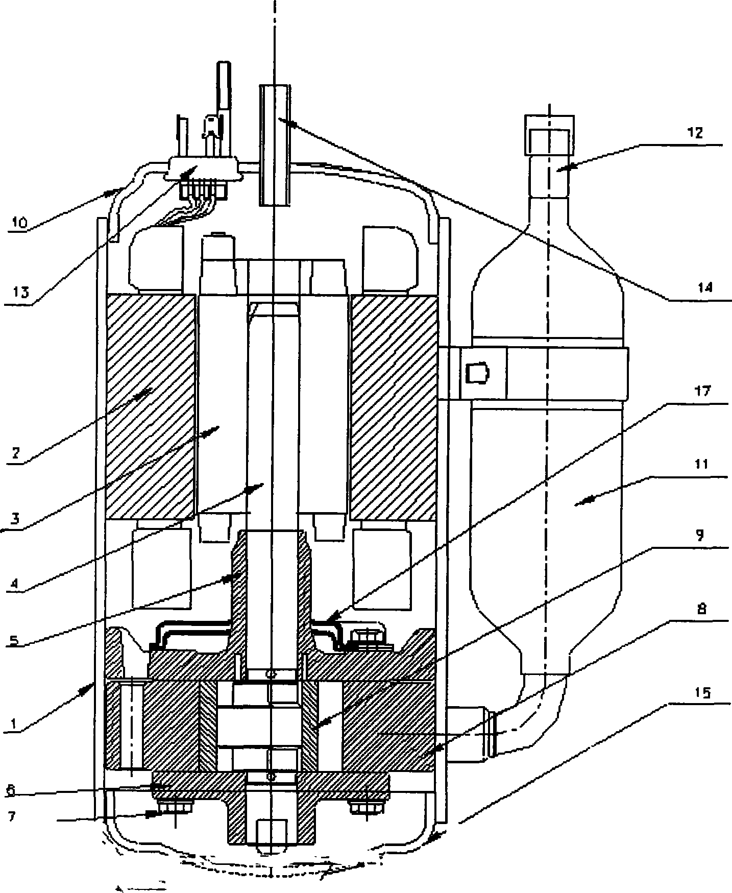
[0025] The working principle of the rotary compressor of the present invention is the same as that of the prior art, and the prior art can be referred to, so it will not be described again. The difference between the present invention and the prior art is the bottom angle of the rotary compressor, which will be described in detail below instruction of:

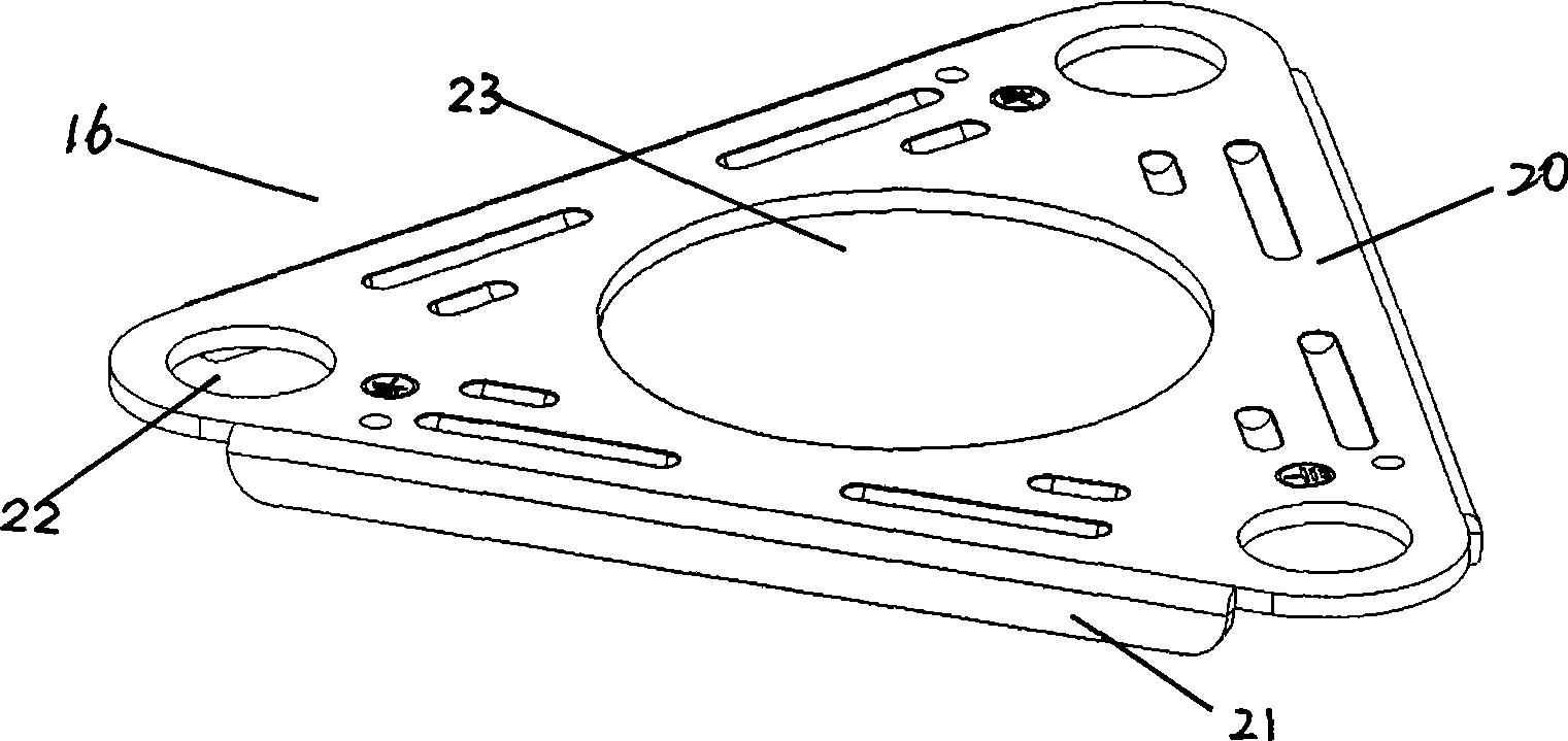
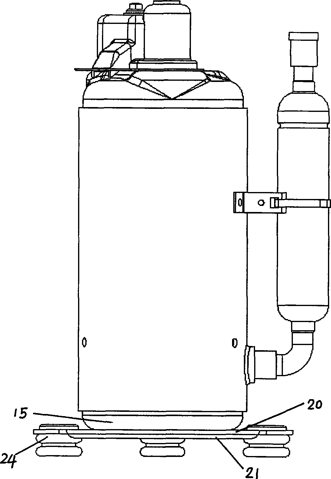
[0026] As shown in Figures 4 and 5, the base angle 26 of the present invention consists of a triangular planar portion 20 and three support ribs 31 positioned below the planar portion 20 along each side of the triangle. The through hole 23 has three mounting holes 22 through the three corners of the triangular planar portion 20 for installing the compressor to the chassis through the bottom angle 26 and inserting the rubber gasket 24. The supporting rib 31 is a long sheet structure with three t...


PUM


Abstract

The invention discloses a base angle of a rotary compressor, which comprises a plane part, a support rib, a through hole and a mounting hole, wherein the support rib is positioned below the plane part along each side thereof; the through hole for mounting the bottom cover of the compressor is arranged at the center of the plane part; the penetrating mounting hole which is used for mounting the compressor on a chassis through the base angle and inserted into a rubber gasket is arranged on the top angle of the plane part; and the support rib adopts a strip structure provided with a plurality of penetrating notches. Each notch is into a shape of a trapezoid with the narrow top and the wide bottom, and the upper bottom of the trapezoid coincides with the lower surface of the plane part. The base angle has the beneficial effects that on the premise of ensuring the stress of a bending edge, the base angle is improved by designing die size; materials are saved after improvement; and a part of bending edge is punched out on the premise of ensuring the stress.

Description

technical field [0001] The present invention relates to the base angle of compressors, especially rotary compressors. Background technique [0002] Generally, such as figure 1 As shown, the prior art rotary compressor includes: a housing 1, a motor part composed of a stator 2 and a rotor 3 inside the housing 1; the bottom of the compressor includes: a cylinder 8 with a certain space compression chamber inside; The fixed crankshaft 4 is pressed into the interior of the rotor 3. There are upper bearing 5 and lower bearing 6 which can support the crankshaft 4. The upper bearing 5 and the lower bearing 6 are fixed with fixed bearing screws 7. The upper part of the upper bearing 5 is provided with a lowering row. The muffler 17 of air noise; the inner surface of the roller ring 9 is in contact with the outer peripheral surface of the eccentric portion at one end of the crankshaft, and the outer peripheral surface of the roller ring 9 is in contact with the inner surface of the c...

Claims


Application Information

Patent Timeline
Patent Type & Authority Applications(China)
IPC IPC(8): F04C29/00
Inventor 韩太亮
Owner LG ELECTRONICS (TIANJIN) APPLIANCES CO LTD
Why Eureka
Try Eureka