Electronically commutated direct current machine sensor-less operation
A DC motor and electronic commutation technology, which is applied in the direction of electronic commutator, electronic commutation motor control, electrical components, etc., can solve the problems of inapplicability and cannot be used to determine the rotor position, and achieve the effect of reducing the number
- Summary
- Abstract
- Description
- Claims
- Application Information
AI Technical Summary
Problems solved by technology
Method used
Image
Examples
Embodiment Construction
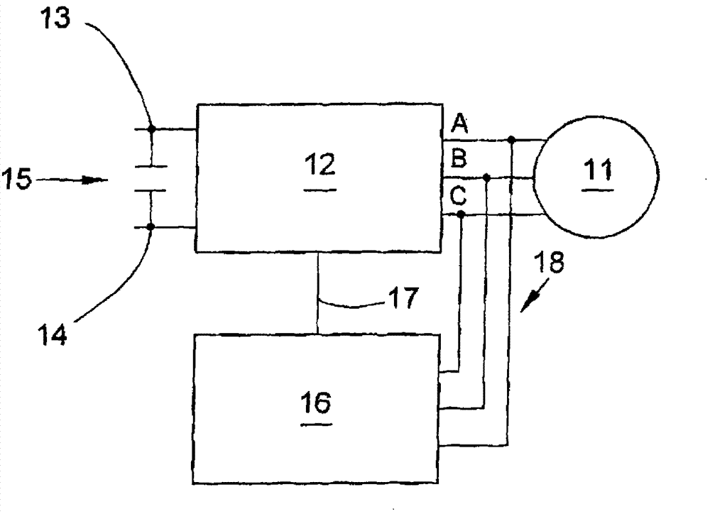
[0040] figure 1 A schematic diagram of an electronic drive according to the invention with an electronically commutated DC motor 11 is shown. The motor 11 consists of three-phase current windings in the stator and a permanent magnet excitation rotor. The connections of the three phases A, B and C are connected to the inverter 12 . The inverter is connected to a DC voltage source. DC voltage source at figure 1 is represented by capacitor 15 and is connected to terminals 13 and 14 of the inverter. The inverter is controlled by the control unit 16 , and the inverter and the control unit are connected to each other by a control line 17 . Measurement lines 18 connect the control device 16 to the three phases A, B and C to measure the induced voltage.
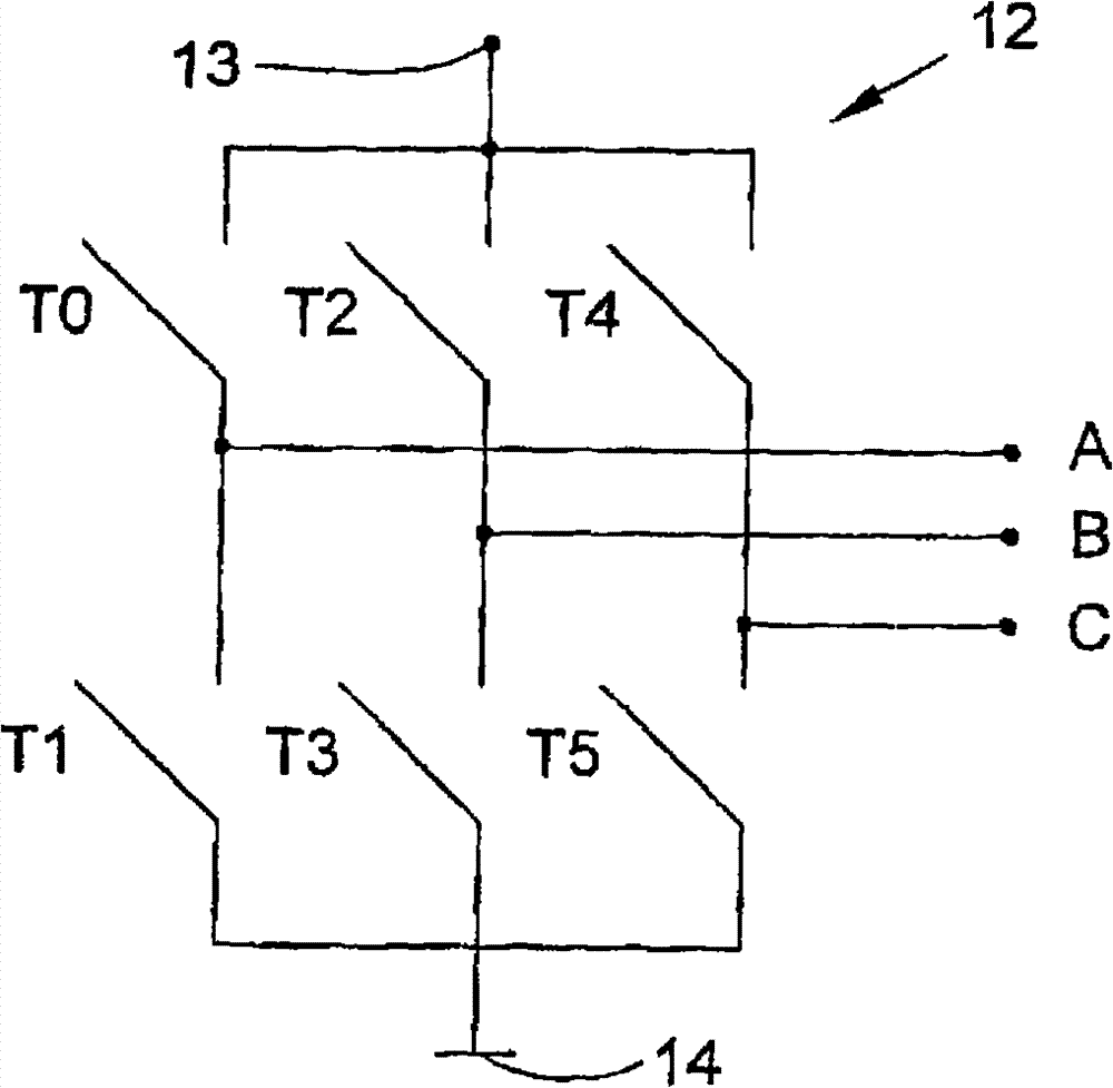
[0041] figure 2 The principle structure of the inverter 12 with the DC voltage connections 13 and 14 and the phase connections A, B and C is shown. The inverter is a three-phase bridge circuit with switches T0 to T5. The swi...
PUM
 Abstract
Description
Claims
Application Information
 - R&D
- Intellectual Property
- Life Sciences
- Materials
- Tech Scout
- Unparalleled Data Quality
- Higher Quality Content
- 60% Fewer Hallucinations
Browse by: Latest US Patents, China's latest patents, Technical Efficacy Thesaurus, Application Domain, Technology Topic, Popular Technical Reports.
© 2025 PatSnap. All rights reserved.Legal|Privacy policy|Modern Slavery Act Transparency Statement|Sitemap|About US| Contact US: help@patsnap.com


