
Feeding device on pipe-winding machine

The technology of a charging device and a pipe bending machine is applied in the directions of feeding device, positioning device, storage device, etc., which can solve the problems of high labor intensity and low work efficiency of workers, reduce labor intensity, improve charging efficiency, and improve The effect of work efficiency

Inactive Publication Date: 2009-03-04
JIANGSU HEFENG MECHANICAL MAKING
View PDF0 Cites 23 Cited by
  • Summary
  • Abstract
  • Description
  • Claims
  • Application Information

AI Technical Summary

Problems solved by technology

The loading in the pipe bending process requires manual operation, the labor intensity of the workers is high, and the work efficiency is low

Method used


Image

  • Feeding device on pipe-winding machine
  • Feeding device on pipe-winding machine

Examples


Embodiment Construction

[0009] Specific embodiments of the present invention will be described in detail below in conjunction with the accompanying drawings.

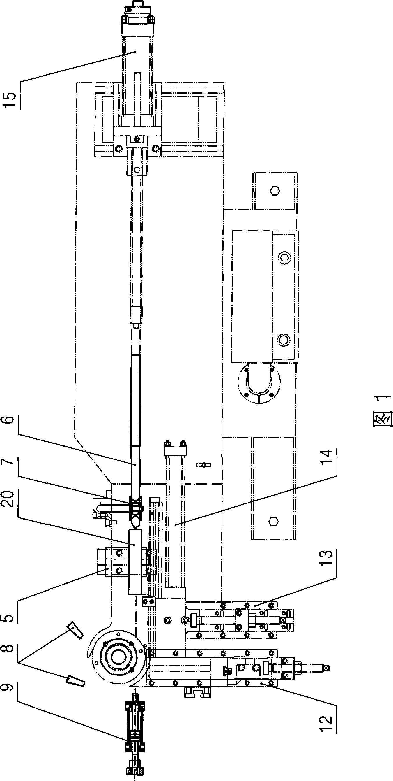
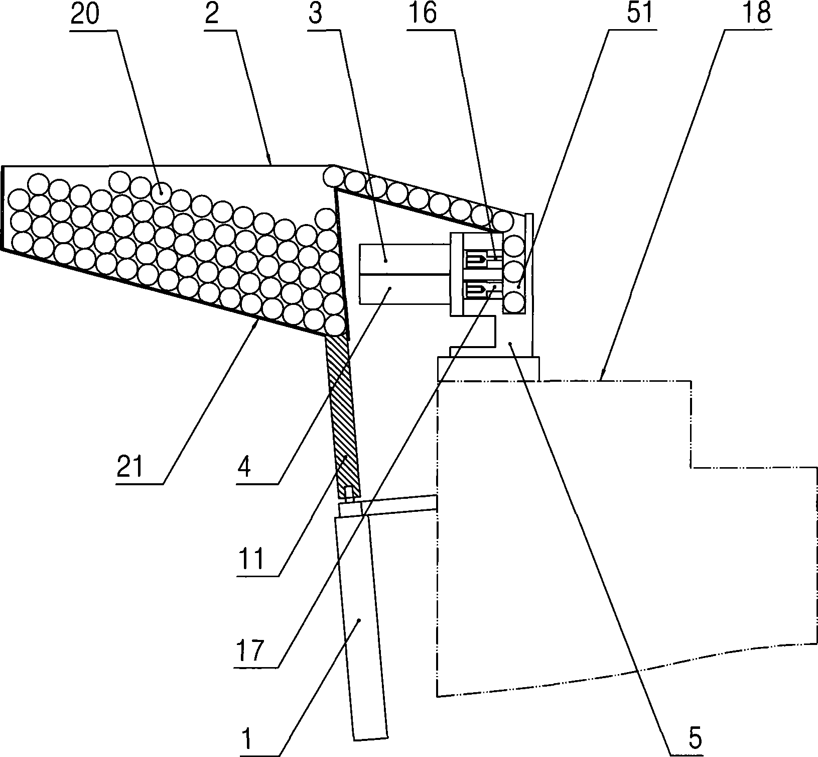
[0010] Such as figure 2 As shown, the charging device on the pipe bender of the present invention-the installation position of the charging device on the pipe bender is shown in Figure 1, including: the material seat 5 arranged on the pipe bender 18, the material seat 5 The upper part of the upper part is provided with a material trough 51, and the side wall on the left side of the material trough 51 is provided with a spacer cylinder 3 and a blanking cylinder 4, the material spacer cylinder 3 is located above the blanking cylinder 4, and the piston rod of the material spacer cylinder 3 is provided with Partition plate 16, the piston rod of blanking cylinder 4 is provided with blanking plate 17, and the material separating plate 16 and blanking plate 17 are all movably pierced in the material chute 51 and are equipped with material separating ...


PUM


Abstract

The invention discloses a loading device on a pipe bending machine which can reduce the labor intensity and improve the work efficiency. The loading device comprises a material seat, a material groove, a material separation cylinder, a blanking cylinder, a piston rod, a material separation board, a blanking board, a material box, a material guiding passage, a material pushing groove and a material pushing board. The material seat is arranged on the pipe bending machine; the material groove is formed on the upper part of the material seat; the material separation cylinder and the blanking cylinder are arranged on the side wall of one side of the material groove; the material separation cylinder is positioned above the blanking cylinder; the material separation board is arranged on the piston rod of the material separation cylinder; the blanking board is arranged on the piston rod of the blanking cylinder; the material separation board and the blanking board are moveably arranged on the side wall of the side of the material groove; the material box is arranged on one side of the material seat; the tilting material guiding passage is arranged at the top of the material box, and the outlet of the material guiding passage is positioned above the material groove; the material pushing groove is formed at the lower end of the tilting bottom of the material box; and the material pushing board is moveably arranged in the material pushing groove and fixed on the piston rod of a material pushing cylinder positioned below the material box. A pipe bending machine provided with the invention is particularly suitable for the bending pipe of short material.

Description

technical field [0001] The invention relates to a pipe bending machine, in particular to a charging device on the pipe bending machine. Background technique [0002] At present, the pipe bending process of the pipe bending machine is: manual loading→manual or trolley feeding→bending→manual unloading; and then repeat this process again and again. The material loading in the pipe bending process requires manual operation, the labor intensity of the workers is high, and the work efficiency is low. Contents of the invention [0003] A technical problem to be solved by the present invention is to provide a charging device on a pipe bending machine that can reduce labor intensity and improve work efficiency. [0004] In order to solve the above-mentioned technical problems, the technical solution adopted in the present invention is: the charging device on the pipe bender, including: a material seat arranged on the pipe bender, a material trough is arranged on the upper part of ...

Claims


Application Information

Patent Timeline
IPC IPC(8): B21D43/00B21D7/00
Inventor 林洪才周炳生
Owner JIANGSU HEFENG MECHANICAL MAKING
Features
  • Generate Ideas
  • Intellectual Property
  • Life Sciences
  • Materials
  • Tech Scout
  • Unparalleled Data Quality
  • Higher Quality Content
  • 60% Fewer Hallucinations
Learn More