
Clamping fixture seat in lock core slot-producing machine

A technology of fixture seat and drawing groove, which is applied in the direction of clamping, broaching machine, broaching machine, etc. It can solve the problems of inability to change, inconvenient installation of fixture seat, and errors, etc., and achieve the effect of convenient installation and positioning

Inactive Publication Date: 2009-03-04
张家港国隆机电五金有限公司
View PDF6 Cites 4 Cited by
  • Summary
  • Abstract
  • Description
  • Claims
  • Application Information

AI Technical Summary

Problems solved by technology

This kind of fixture seat has very high requirements on its own positioning holes and the positioning holes on the frame, because once the positioning holes are determined, the position of the fixture seat on the frame cannot be changed
In fact, the positioning cannot be 100% accurate, and there will always be errors. Once the positioning is not accurate, it will be difficult to adjust the installation position of the fixture seat
This brings inconvenience to the installation of the fixture seat

Method used


Image

  • Clamping fixture seat in lock core slot-producing machine
  • Clamping fixture seat in lock core slot-producing machine

Examples


Embodiment Construction

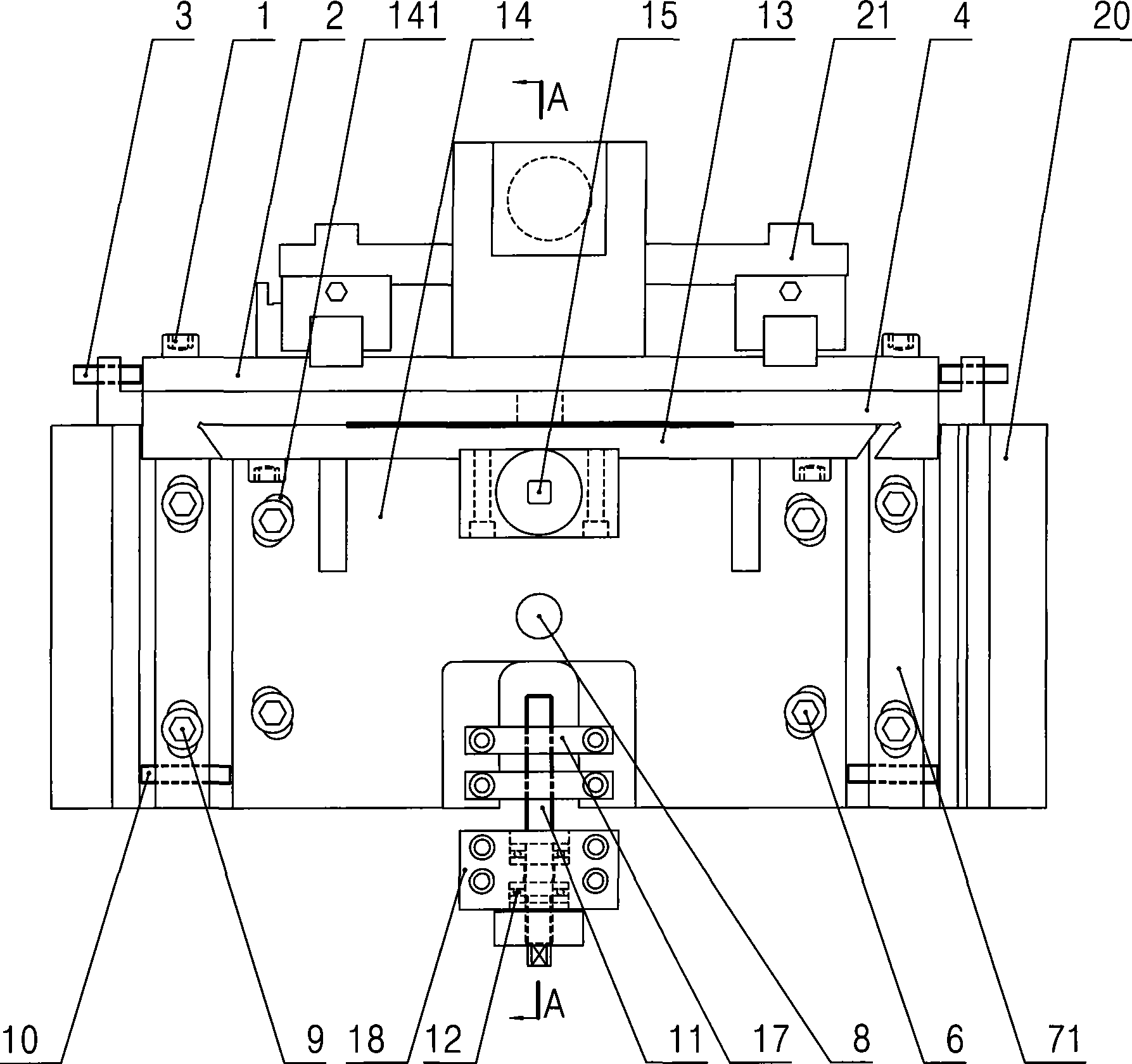
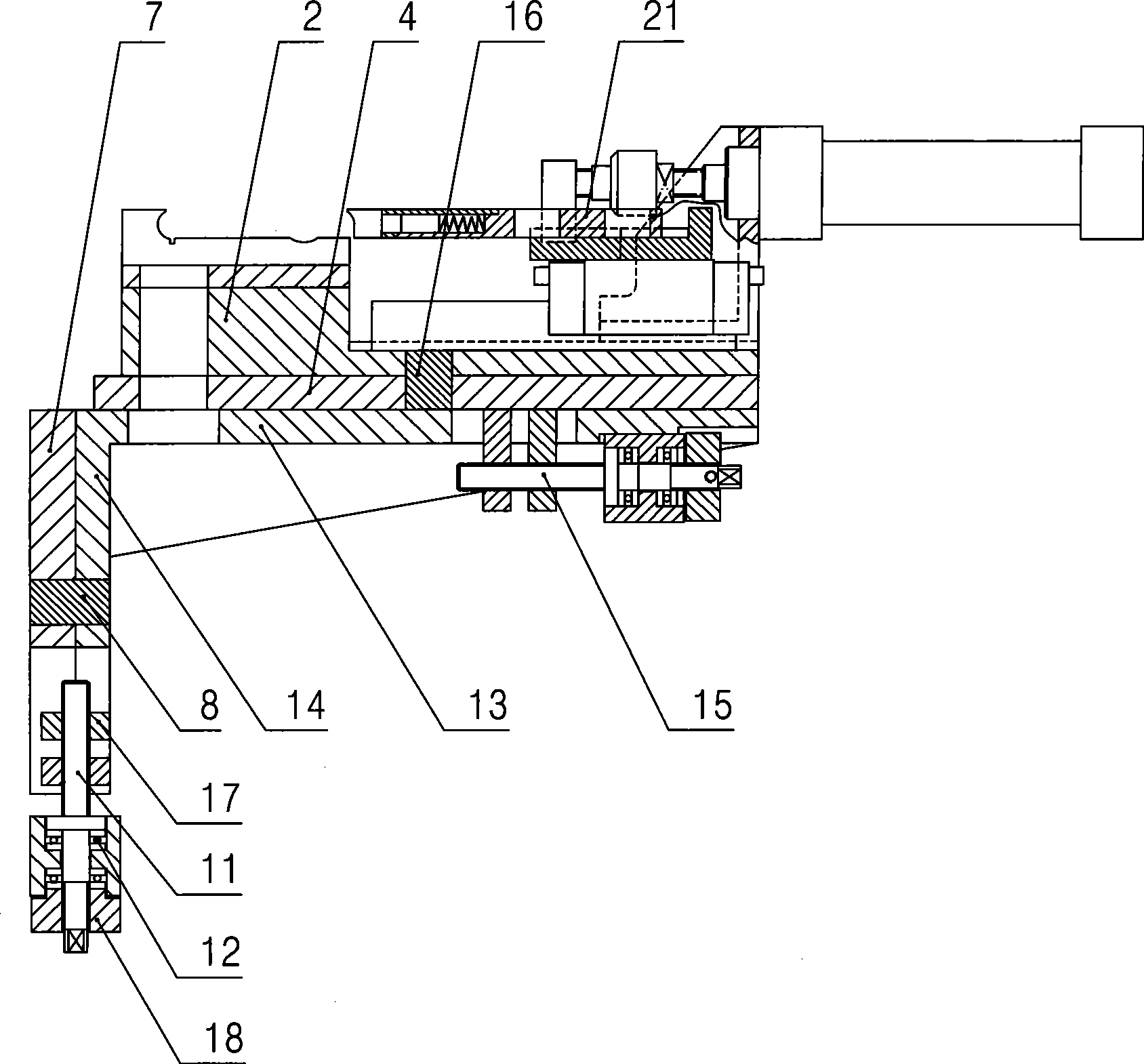
[0012] Specific embodiments of the present invention will be described in detail below in conjunction with the accompanying drawings.

[0013] Such as figure 1 , figure 2 As shown, the clamp seat in the lock cylinder slotting machine of the present invention includes: a rotating base 2 for placing a clamp 21, a translation platform 4, an L-shaped support base and a base 7, wherein: the L-shaped support base is composed of The horizontal seat 13 and the vertical seat 14 are formed, the bottom of the rotary seat 2 is provided with a rotary shaft 16, and the rotary shaft 16 is movably arranged in the translation platform 4, and a horizontal positioning locking mechanism is arranged between the rotary seat 2 and the translation platform 4, and The specific setting method is: at least two circular arc long holes are provided in the rotating base 2, and the threaded holes corresponding to the circular arc long holes are provided on the described translation platform 4, and the loc...


PUM


Abstract

The invention discloses a clamping fixture holder with adjustable mounting positions in a lock core groove broacher. The clamping fixture holder comprises a rotary holder used for mounting a clamping fixture, and the clamping fixture holder further comprises a translational platform, an L-shaped support holder and a base, wherein a rotating shaft is arranged at the bottom of the rotary holder andmovably arranged in the translational platform; a horizontal positioning locking mechanism is arranged between the rotary holder and the translational platform; the L-shaped support holder is composed of a horizontal holder and a vertical holder; the bottom part of the translational platform is movably arranged on the horizontal holder; a rotation shaft is arranged on the vertical holder and movably arranged in the base; a vertical positioning locking mechanism is arranged between the vertical holder and the base; and at least two slotted holes are formed on the base which is fixed on a broacher frame by locking screws penetrating the slotted holes, therefore, the clamping fixture holder allows the multi-directional adjustment which greatly facilitates mounting and positioning of the clamping fixture on the broacher frame.

Description

technical field [0001] The invention relates to a lock cylinder slotting machine, in particular to a clamp seat in the lock cylinder slotting machine. Background technique [0002] As we all know, the structure of the fixture seat in the traditional lock cylinder slotting machine is very simple, which is a base for installing the fixture on the frame, and the base and the frame are provided with positioning holes that cooperate with each other. This kind of fixture seat has very high requirements on its own positioning holes and the positioning holes on the frame, because once the positioning holes are determined, the position of the fixture seat on the frame cannot be changed. In fact, the positioning cannot be 100% accurate, and there will always be errors. Once the positioning is not accurate, it will be difficult to adjust the installation position of the fixture seat. This brings inconvenience to the installation of the fixture seat. Contents of the invention [000...

Claims


Application Information

Patent Timeline
IPC IPC(8): B23D41/06B23Q3/06
Inventor 谢金木
Owner 张家港国隆机电五金有限公司
Learn More