Dual band stacked patch antenna

A patch antenna, dual-band technology, used in antennas, resonant antennas, electrical short antennas, etc., can solve problems such as increasing complexity, cost, and complex configuration

Inactive Publication Date: 2009-03-04
GM GLOBAL TECH OPERATIONS LLC
View PDF1 Cites 39 Cited by
  • Summary
  • Abstract
  • Description
  • Claims
  • Application Information

AI Technical Summary

Problems solved by technology

The disadvantage of this second design is that the configuration is relatively complex and requires two different feed elements, which increases the complexity and cost of the final assembly to the vehicle

Method used


Image

  • Dual band stacked patch antenna
  • Dual band stacked patch antenna
  • Dual band stacked patch antenna

Examples


Embodiment Construction

[0021] The following detailed description is merely exemplary in nature and is not intended to limit the invention or the application and uses of the invention. Furthermore, there is no intention to be bound by any expressed or implied theory presented in the preceding technical field, background, brief summary, or the following detailed description.

[0022] For the sake of brevity, conventional techniques and aspects related to GPS systems, SDARS systems, RF / microwave antenna design, and RF / microwave signal propagation will not be described in detail herein. Additionally, those skilled in the art will understand that the embodiments of the dual-band patch antenna described herein may be practiced on any set of two or more frequency bands, in conjunction with any number of applications and devices, and that the embodiments described herein Vehicle placement is but one suitable example.

[0023] The following description refers to elements or nodes, or features being "connect...


PUM


Abstract

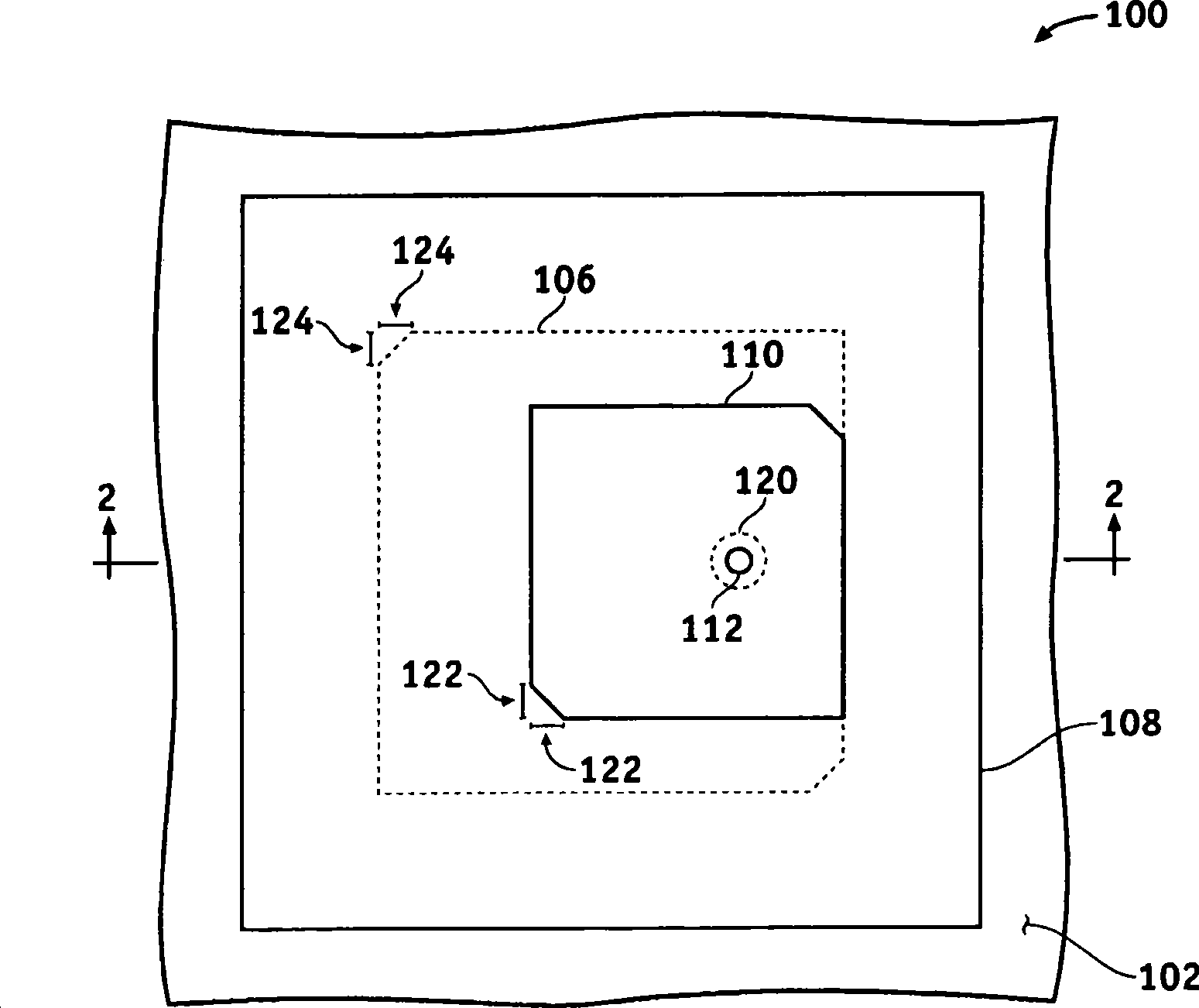
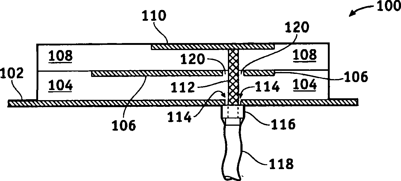
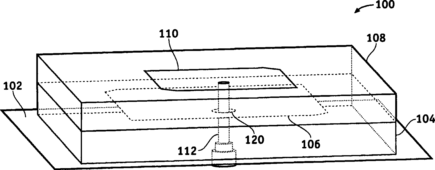
One or more of the embodiments of a dual band stacked patch antenna described herein employ an integrated arrangement of a global positioning system (GPS) antenna and a satellite digital audio radio service (SDARS) antenna. The dual band antenna receives right hand circularly polarized GPS signals in a first frequency band, left hand circularly polarized SDARS signals in a second frequency band, and vertical linear polarized SDARS signals in the second band. The dual band antenna includes a ground plane element, an upper radiating element (which is primarily utilized to receive SDARS signals), dielectric material between the ground plane element and the upper radiating element, and a lower radiating element (which is primarily utilized to receive GPS signals) surrounded by the dielectric material. The dual band antenna uses only one conductive signal feed to receive both GPS and SDARS signals.

Description

technical field [0001] The subject matter described herein relates generally to patch antennas, and more particularly to an integrated dual-band stacked patch antenna suitable for use with Global Positioning System (GPS) signals and Satellite Digital Audio Radio Service (SDARS) signals. Background technique [0002] Existing techniques include radio frequency (RF) and microwave antenna design, construction and configuration. Such antennas are utilized in many different applications to wirelessly transmit and receive signals conveying information or data. For example, a modern automobile (or other vehicle) may utilize many antennas to receive signals throughout the radio frequency spectrum. Indeed, the vehicle may include one or more of the following systems: AM / FM radio; satellite radio; GPS-based navigation system; and mobile telecommunications system. Certain vehicles may include antennas to receive SDARS signals and / or GPS signals. In this case, L1 GPS signals are used...

Claims


Application Information

Patent Timeline
Patent Type & Authority Applications(China)
IPC IPC(8): H01Q1/38H01Q5/00H01Q21/30H01Q9/16H01Q5/10H01Q5/378
CPCH01Q5/378H01Q9/0414H01Q5/0062
Inventor K·吉尔里J·H·谢夫纳H·-P·苏J·S·科尔伯恩H·J·宋
Owner GM GLOBAL TECH OPERATIONS LLC
Why Eureka
Try Eureka