Stepping motor

A technology for stepping motors and holding parts, applied in the direction of electrical components, electromechanical devices, etc., can solve the problem of increasing the space for installing stepping motors 500, and achieve the effect of preventing accidental tilting

Inactive Publication Date: 2009-03-04
SANKYO SEIKI MFG CO LTD
View PDF2 Cites 3 Cited by
  • Summary
  • Abstract
  • Description
  • Claims
  • Application Information

AI Technical Summary

Problems solved by technology

However, in this configuration, if Figure 17 As shown in (b), the power supply substrate 510 connected to the terminal pins 501a to 501d protrudes from the longitudinal direction of the motor body (stator) 502 ( Figure 17 The slanted part of (b)), there is a problem that the space required for mounting the stepping motor 500 increases

Method used


Image

  • Stepping motor
  • Stepping motor
  • Stepping motor

Examples


Embodiment Construction

[0081] (first embodiment)

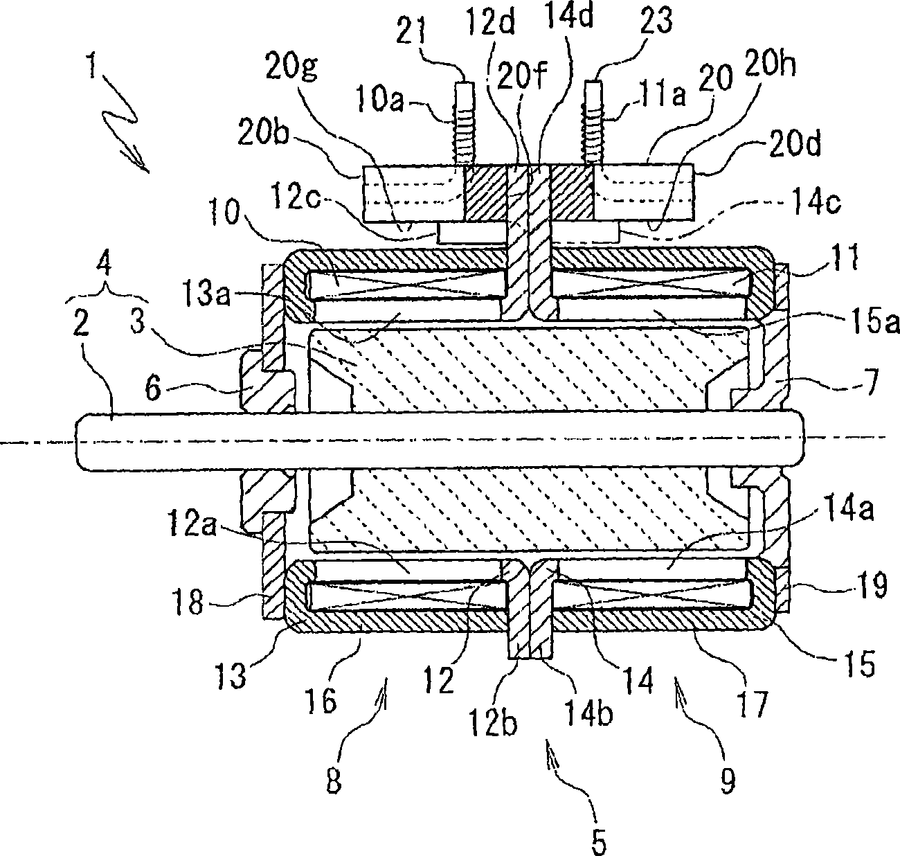
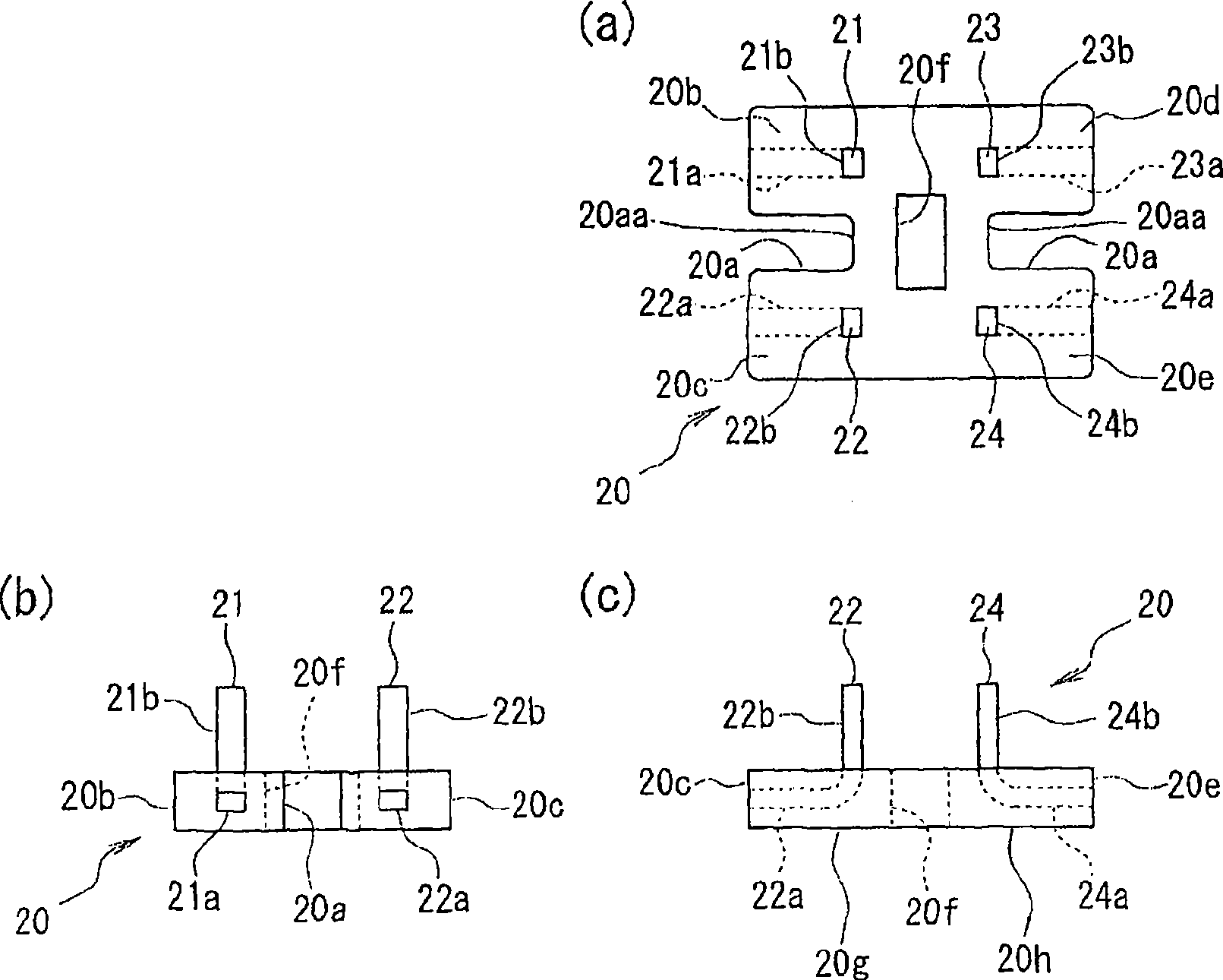
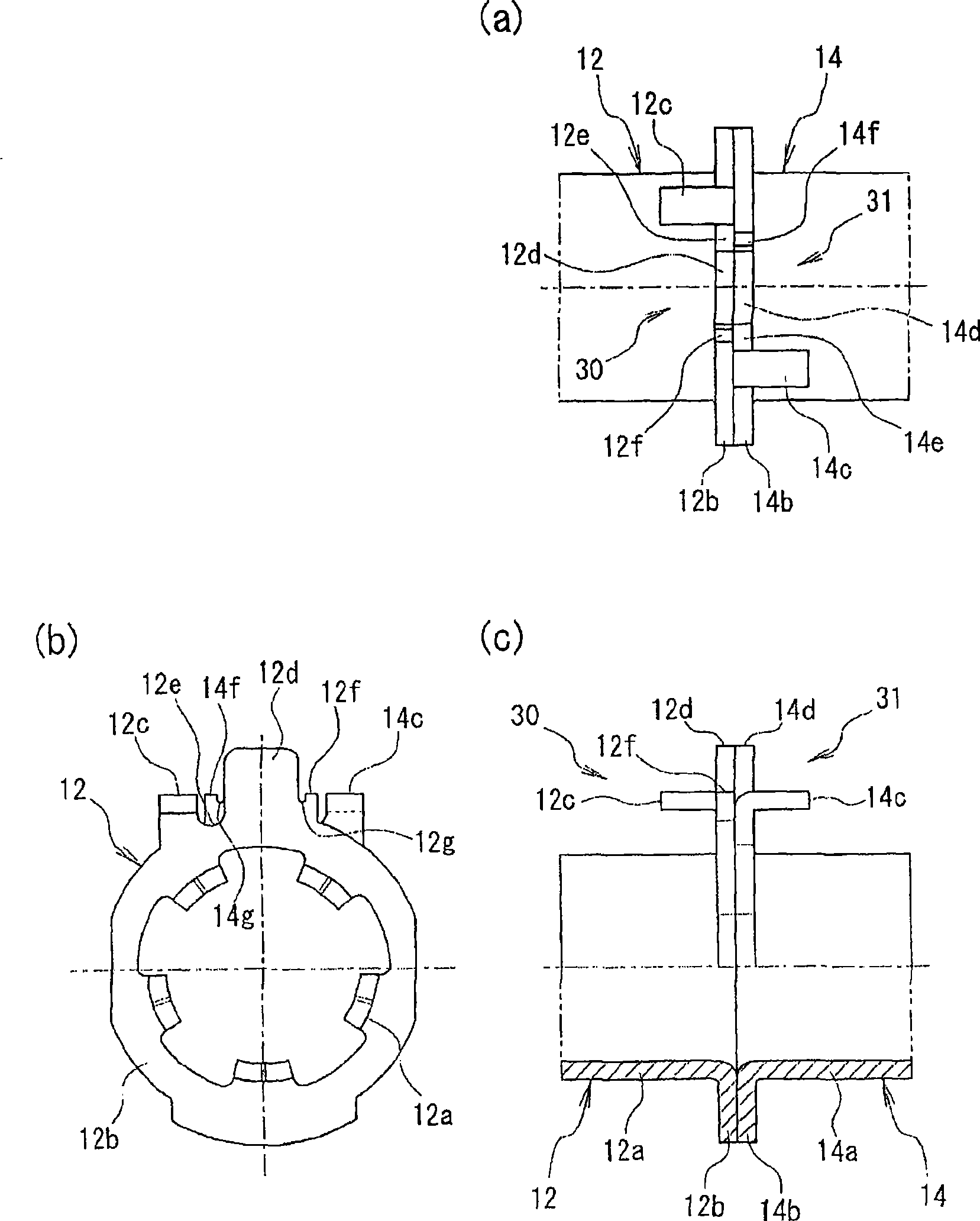
[0082] An embodiment of the stepping motor of the present invention will be described in detail below with reference to the drawings. The first embodiment describes the first invention. figure 1 is a sectional side view showing a schematic structure of a stepping motor according to a first embodiment of the present invention, figure 2 It is a figure showing a terminal block. figure 2 (a) is a plan view, figure 2 (b) is a side view, figure 2 (c) is a front view. image 3 is a diagram showing the inner stator core, image 3 (a) is a plan view, image 3 (b) is a side view, image 3 (c) is a front view showing a part cut away. Figure 4 It is a figure showing the state in which the terminal block is fixed to the inner stator core, Figure 4 (a) is a plan view, Figure 4 (b) is a side view, Figure 4 (c) is a front view showing a part cut away.

[0083] figure 1 The illustrated stepping motor 1 includes a rotor 4 having a shaft 2 and a...


PUM


Abstract

A stepping motor can prevent the careless inclining of terminal stand arranged at the periphery side of stepping motor. The stepping motor comprises the following components: a rotor which comprises a rotation shaft and a permanent magnet provided surrounding the periphery of rotation shaft; a stator which comprises a stator core that is vertical and formed with pole teeth; a driving coil which is arranged at the periphery side of the pole teeth; and the terminal stand which is arranged at the periphery side of stator. The brim part of stator core is arranged with a terminal stand holding part holding the terminal stand. The terminal stand holding part is formed with a first holding part supporting the bottom surface of terminal stand. The first holding part bends and extends in the direction from the brim part to the axial cord.

Description

technical field [0001] The invention relates to a stepping motor with a terminal block. Background technique [0002] In the past, in such Figure 16 In the small-sized stepping motor 60 shown in (a), the terminal block 62 formed of a resin material to which a plurality of terminal pins 61 is attached is provided on the outer peripheral side of the stepping motor 60 . The winding ends to which the coils 63 and 64 are connected are wound around the terminal pin 61 . [0003] A fitting hole 62a is formed in the center of the terminal block 62, and the holding parts 65b, 66b extending from the eaves 65a, 66a of the stator cores 65, 66 arranged back to back are fitted into the fitting hole 62a, and the The terminal block 62 is fixed. Figure 16 The top view of (b) and Figure 16 The front views of (c) respectively show the stator cores 65 and 66 in a state where the terminal block 62 is fixed (see Patent Document 1). [0004] In addition, among other conventional stepping moto...

Claims


Application Information

Patent Timeline
Patent Type & Authority Applications(China)
IPC IPC(8): H02K37/14
Inventor 矢岛克英
Owner SANKYO SEIKI MFG CO LTD
Why Eureka
Try Eureka