Tunnel air pollutant purification apparatus

A technology of tunnel air and purification device, applied in the field of air purification, can solve the problems such as the inability to meet the requirements of tunnel air pollutant control, and achieve the effect of improving efficiency

Inactive Publication Date: 2009-03-11
SHANGHAI NAT ENG RES CENT FORNANOTECH
View PDF1 Cites 18 Cited by
  • Summary
  • Abstract
  • Description
  • Claims
  • Application Information

AI Technical Summary

Problems solved by technology

Therefore, the need for existing technology can not meet...

Method used


Image

  • Tunnel air pollutant purification apparatus
  • Tunnel air pollutant purification apparatus

Examples


Embodiment 1

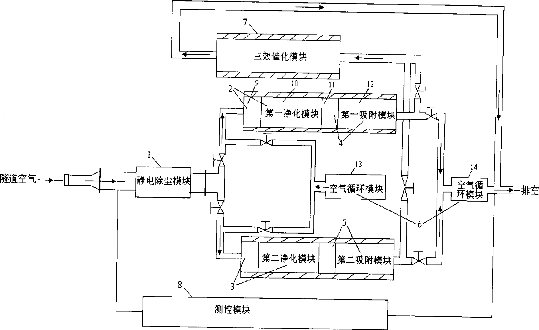
[0029] like figure 1 As shown, this embodiment includes: electrostatic dust removal module 1, first purification module 2, second purification module 3, first adsorption module 4, second adsorption module 5, air circulation module 6, three-way catalytic module 7 and measurement and control module 8, wherein: the input end of the electrostatic precipitator module 1 receives tunnel air, the output end of the electrostatic precipitator module 1 is respectively connected to the input ends of the first purification module 2 and the second purification module 3 and the air inlet of the air circulation module 6, the first The output ends of the purification module 2 and the second purification module 3 are respectively connected to the input ends of the first adsorption module 4 and the second adsorption module 5, and the output ends of the first adsorption module 4 and the second adsorption module 5 are connected to the air circulation module 6 respectively. The exhaust port and the...

Embodiment 2

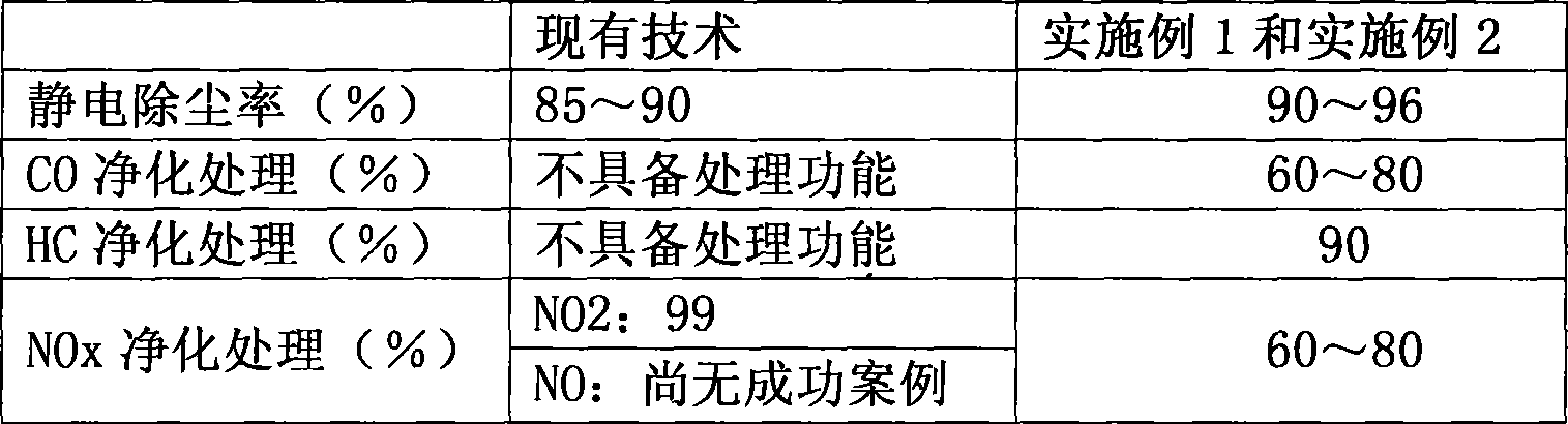
[0046] In Example 2, air purification is carried out in the following manner: the CO purification chamber 10 is filled with 150 to 360 m of modified Ag catalysts that are supported by monolithic honeycomb ceramics. 3 , fill the adsorption chamber 12 with 200-450m of modified monolithic honeycomb activated carbon 3 , the temperature of the two chambers is 5-55°C; the three-way catalytic module 7 is loaded with a modified Pd / Pt three-way catalyst supported by monolithic honeycomb ceramics for 80-120m 3 , the temperature inside the three-way catalytic module is 150-300°C; the processing air volume is 360,000-720,000 m 3 / h; the initial contents of PM, CO, NOx and HC in tunnel air are 5-6 mg / m respectively 3 , 20-40ppm, 5-6ppm and 10-20ppm, the dust removal rate is 90-96%, the CO catalytic oxidation removal rate is 60-75%, and the NOx and HC adsorption removal rates are 60-80% and 90% respectively ; When the adsorption chamber 12 is filled with modified monolithic honeycomb acti...


PUM


Abstract

The invention relates to a device for purifying tunnel air pollutants in the technical field of air purification. The device comprises an electrostatic precipitation module, an air circulation module, a three way catalyst module, a measurement and control module, at least one purification module and at least one absorption module, wherein, the input terminal of the electrostatic precipitation module receives the tunnel air, the output terminal of the electrostatic precipitation module is respectively connected with the input terminal of the purification module and the air inlet of the air circulation module, the output terminal of the purification module is connected with the input terminal of the absorption module, the output terminal of the absorption module is respectively connected with the air outlet of the air circulation module and the input terminal of the three way catalyst module, and the output terminal of the three way catalyst module and the air outlet of the air circulation module discharge the pollutant to the air directly. The device can effectively avoid the phenomenon that temperature is out of control, a purification chamber and an absorption chamber are made from high temperature resistant material, and the thermal expansion coefficient is small; and examination, automatic control and safety warning are carried out by the measurement and control module.

Description

technical field [0001] The invention relates to a device in the technical field of air purification, in particular to a tunnel air pollutant purification device. Background technique [0002] Foreign countries mainly adopt two methods for purifying air pollutants in tunnels: (1) Usually, a high-altitude wind tower is built at the exit of a short tunnel for high-volume high-altitude exhaust, and electrostatic dust removal equipment and NO2 removal devices are installed in the wind tower to control the air pollution of the tunnel. (2) Add side lines inside the long tunnel, install dust removal devices and a small amount of ventilation devices in the side line tunnels to reduce the demand for fresh air and the number of air shafts, and achieve the purpose of reducing the impact of pollutants on the external environment of the tunnel . However, there are difficulties in the construction or site selection of wind shafts, and the addition of side tunnels will greatly increase the...

Claims


Application Information

Patent Timeline
IPC IPC(8): B01D50/00B01D53/00
Inventor 姚炜张豪杰卢冠中施剑林叶国强何丹农
Owner SHANGHAI NAT ENG RES CENT FORNANOTECH
Why Eureka
Try Eureka