
Wind energy collecting fan

A fan and wind energy technology, applied in the field of new wind energy collection fans, can solve the problems of increased friction, scrapped wind energy utilization devices, low energy conversion rate of wind energy utilization devices, etc.

Inactive Publication Date: 2009-03-11
丛兴陆
View PDF0 Cites 0 Cited by
  • Summary
  • Abstract
  • Description
  • Claims
  • Application Information

AI Technical Summary

Problems solved by technology

The disadvantage of the current wind energy fan is that it takes up a lot of space and cannot make good use of the wind energy in the vertical direction; because it works on a horizontal plane, the gravity causes the bearing to always rub against its bottom, and the uneven friction of the bearing leads to increased friction, which makes the entire wind energy utilization device The energy conversion rate is low, and even some wind energy utilization devices are scrapped after installation

Method used


Image

  • Wind energy collecting fan
  • Wind energy collecting fan

Examples


Embodiment Construction

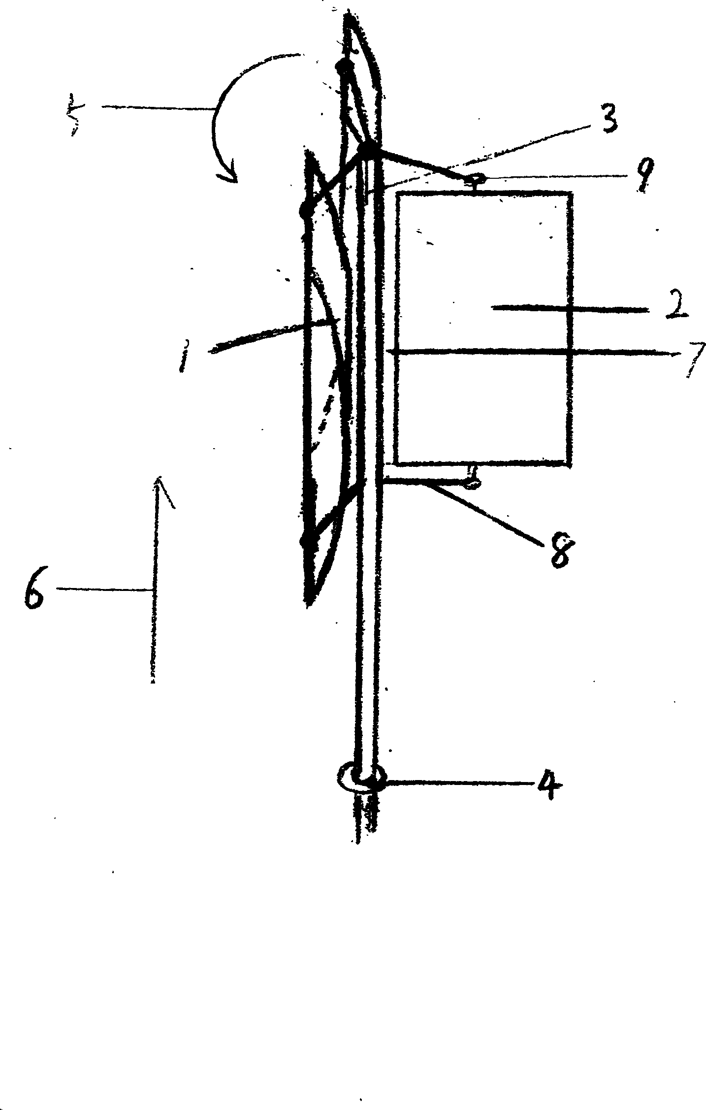
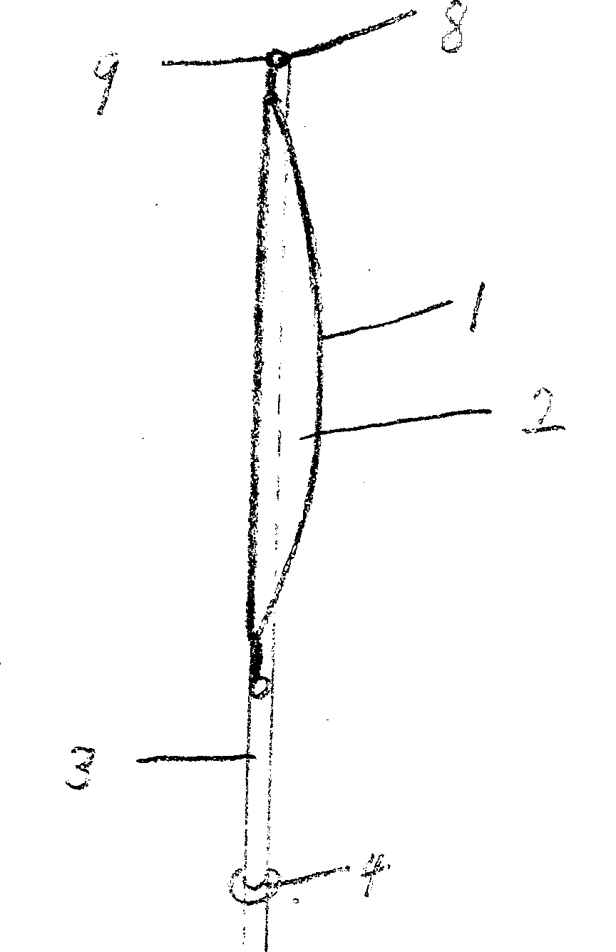
[0010] In the figure, the surface of the blade (2) is not a plane but a blade depression (1). Since the blade (2) has a blade depression (1) that can better collect wind energy, the blade (2) is fixed on the fan by the blade fixing bracket (8). (7), the blade (2) and the blade fixing bracket (8) are connected by the blade fixing bracket and the blade connecting bearing (9), so that a single blade (2) can rotate by itself, and the fan shaft (3) and the bearing (4) are The connection is perpendicular to the ground direction (6), so that the friction of the bearing (4) is more uniform; the fan shaft rotation direction (5) is shown in the figure.


PUM


Abstract

The invention relates to a wind energy fan, which can effectively collect wind energy and reduce the energy loss. The wind energy fan consists of automatically rotated blades, and the blades have hollow surfaces.

Description

Technical field [0001] The invention belongs to a novel wind energy collection fan. Background technique [0002] At present, the known wind energy fans are three-needle blades, and the fan shaft is installed in a horizontal direction. The disadvantage of the current wind energy fan is that it takes up a lot of space and cannot make good use of the wind energy in the vertical direction; because it works on a horizontal plane, the gravity causes the bearing to always rub against its bottom, and the uneven friction of the bearing leads to increased friction, which makes the entire wind energy utilization device The energy conversion rate is low, and even some wind energy utilization devices are scrapped after installation. Contents of the invention [0003] In order to overcome the deficiencies in the design of current wind energy collection devices and improve the conversion rate of wind energy. [0004] The technical scheme designed by the present invention is to design ...

Claims


Application Information

Patent Timeline
IPC IPC(8): F03D3/06
CPCY02E10/74
Inventor 丛兴陆
Owner 丛兴陆
Learn More