
Water tank improvements

a technology for water tanks and tanks, applied in the field of water tanks, can solve the problems of high pressure at and toward the bottom of the tank, many people are undesirable, and internal bracing at first sight is not an option

Inactive Publication Date: 2011-10-06
THIN TANKS
View PDF47 Cites 0 Cited by
  • Summary
  • Abstract
  • Description
  • Claims
  • Application Information

AI Technical Summary

Benefits of technology

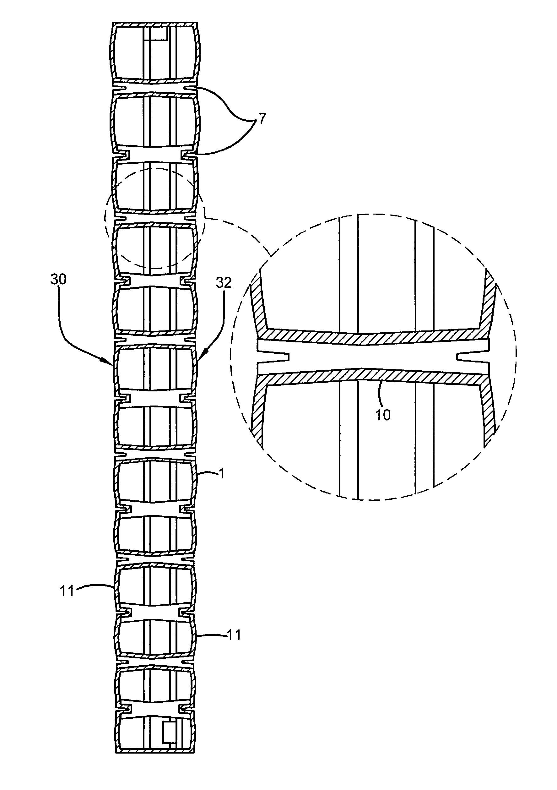
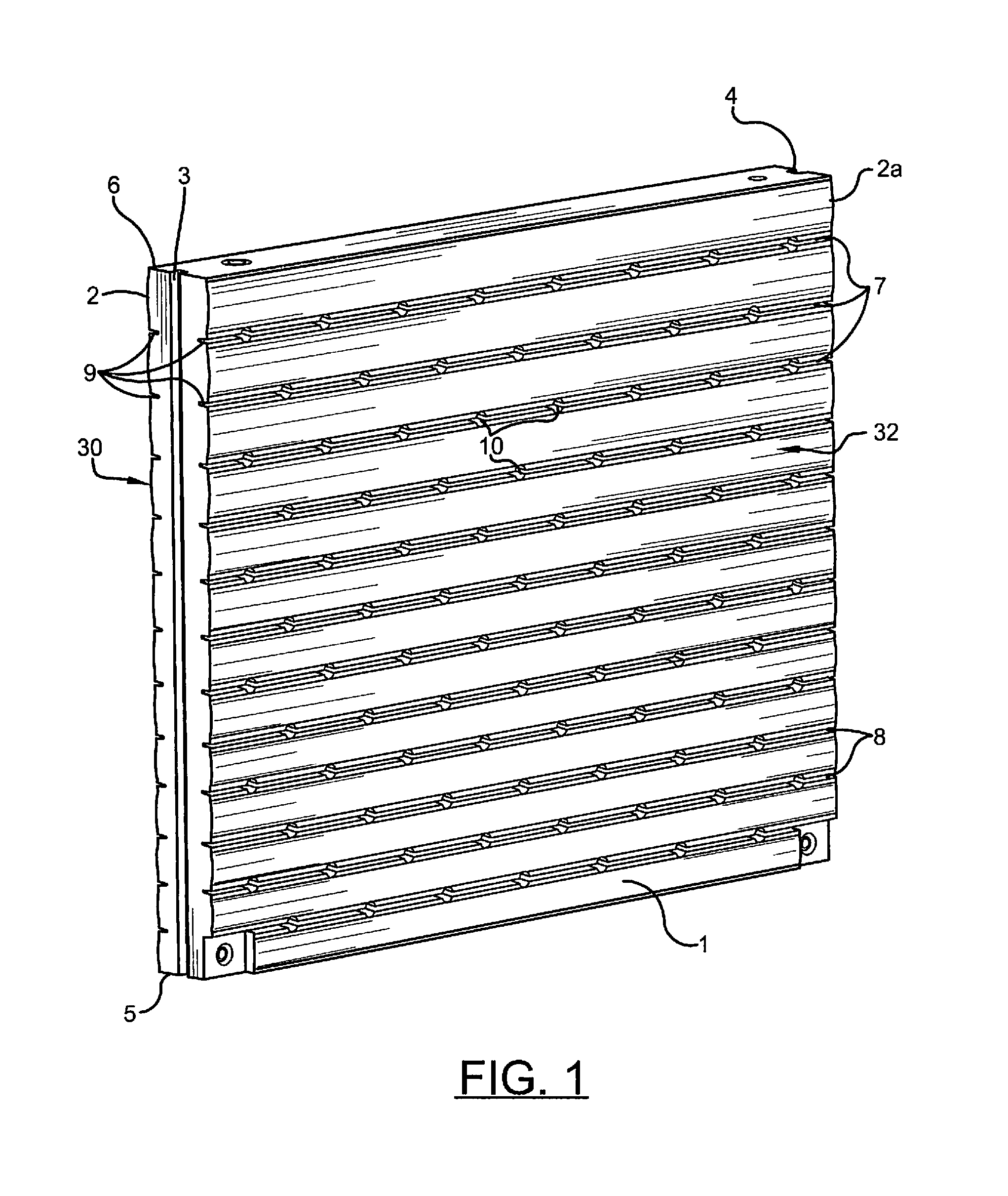
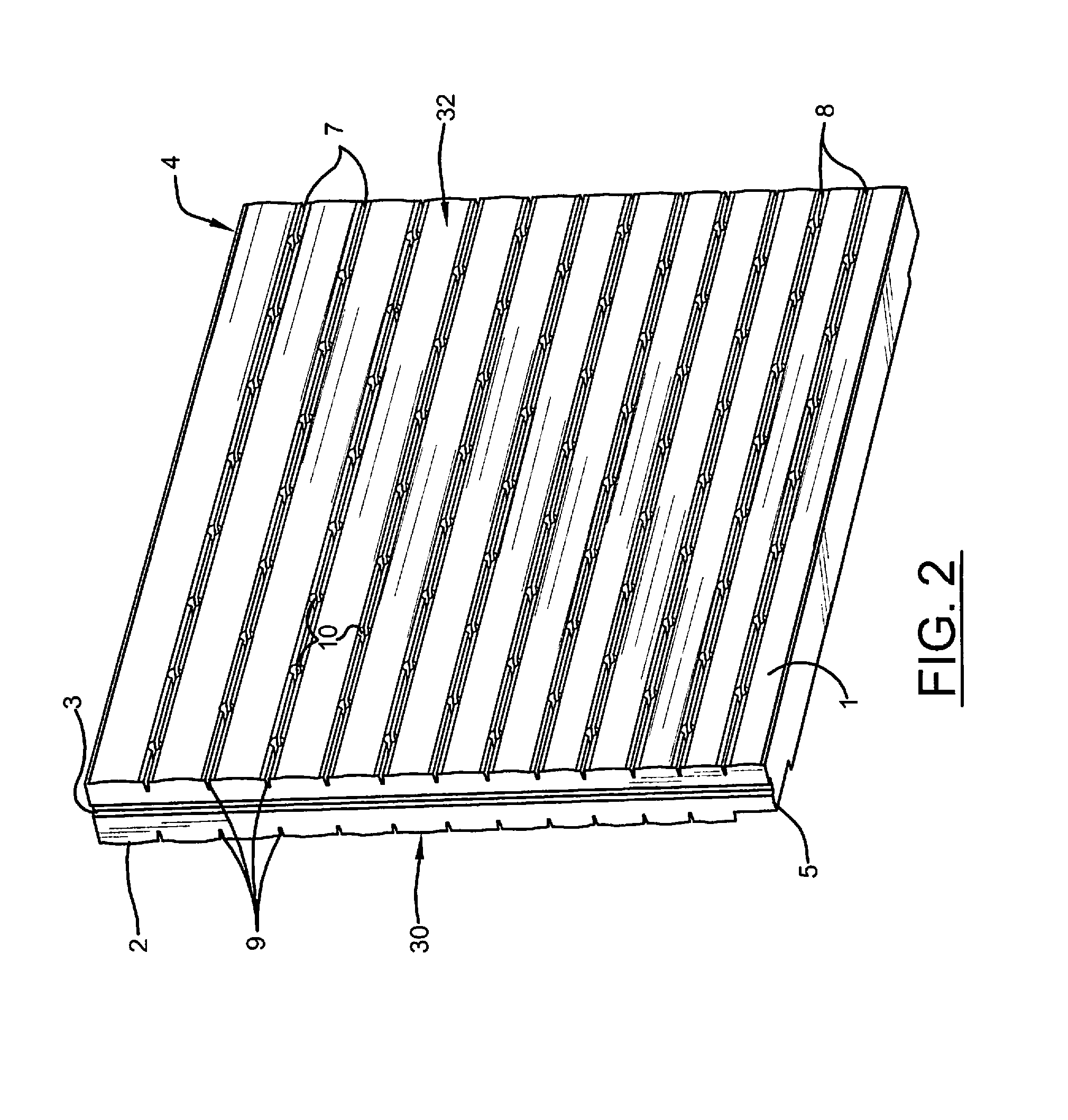
The inset channels can be relatively straightforwardly moulded from plastic by using for instance a rotational moulding technique and by having such channels moulded at spaced apart intervals in a vertical spaced alignment. The spacing can be selected and the depth of the channel selected to accord with the head height and length of a tank which can then be chosen in accordance with a desirable storage capacity. It has been discovered that if one uses this technique, some advantage can be obtained by increasing the vertical spacing of the laterally extending reinforcing channels at an upper part of the tank as compared to a lower part of the tank. This is because the burst pressure of a head of water is directly proportional to the depth of water.
This allows the length of a tank to be chosen to allow for sufficient strength in line with head height but not having to suffer undue interruptions within a visual appearance.
This has the advantage that it does implicitly stiffen the wall segment thus shaped but it also relieves the view of seeing a perfectly planar surface where any bulging will be much more apparent than if there is in effect a slight bulging on a controlled basis where a little more bulging will not be so apparent.

Problems solved by technology

One of the difficulties with tanks in general is that in order to store a reasonable quantity of water, they will need to have a relatively deep storage area and the difficulty here is that this will cause relatively high pressures at and toward the bottom of the tank when filled with water due simply to the head of water within the tank.
Another and perhaps more significant problem relates to appearance.
External bracing implicitly contributes significant mechanical parts to the visual appearance and to many people is undesirable purely from an appearance point of view.
Internal bracing at first sight is not an option because of the narrowness between the broad sides which limits access at least for subsequent installation.
Further however, in order to achieve adequate bracing strength, the elements providing such bracing must be substantial and any plastic wall in order to accommodate such bracing has either to be moulded to allow for a substantial insetting of such reinforcing members or, if they are positioned to extend proud of a side wall, then these can add significantly to the overall width of such a tank and can thereby implicitly destroy or at least reduce its advantage of being thin and still hold a reasonable quantity of water.

Method used


Image

  • Water tank improvements
  • Water tank improvements
  • Water tank improvements

Examples


Embodiment Construction

Referring specifically to the drawings FIGS. 1 through 6, a particular, non-limiting embodiment of a tank 1 in accordance with this invention is moulded by rotational moulding and has dimensions where the width, which is to say the maximum distance apart of the first side wall 30 and second side wall 32, is 230 millimeters (mm), the height is 1850 mm and the length is 2400 mm. These dimensions provide capacity in the tank for close to 1000 litres of water.

While this invention is not to be limited to or by and particular dimensions, the width is preferably kept small, between 200 and 300 mm, and, in other embodiments, is below 250 mm.

Each tank has an embedded channel 3 at one end 2, and an embedded channel 4 at the opposite end 2a, each embedded channel 3 and 4 extending fully from a bottom wall 5 of the tank to a top wall 6 of the tank. The ends 2 and 2a may be considered as left and right end walls.

Extending laterally between the ends 2 and 2a of the tank, are a plurality of reinfo...


PUM

PropertyMeasurementUnit
Distanceaaaaaaaaaa
Shapeaaaaaaaaaa

Abstract

A thin tank integrally molded by rotational molding of plastics material with a plurality of laterally extending channels with interconnecting ties between correspondingly positioned channels. End channels are inset into each end wall to provide interlocking engagement with a support post or bracket.

Description

TECHNICAL FIELDThis invention relates to a water tank and in particular to one formed from plastics material and is dimensioned so that it can be generally described as a “thin” tank.BACKGROUND OF THE INVENTIONWith the current prospect of global warming and fears of increasing lack of potable water, water tanks that can be located in some more difficult locations is desirable.This is particularly the case with a tank that has a relatively small width so that it can be located in places where space is very limited or in places where it is convenient to have a relatively thin barrier as for instance in a fencing application.One of the difficulties with tanks in general is that in order to store a reasonable quantity of water, they will need to have a relatively deep storage area and the difficulty here is that this will cause relatively high pressures at and toward the bottom of the tank when filled with water due simply to the head of water within the tank.Another and perhaps more si...

Claims


Application Information

Patent Timeline
IPC IPC(8): B65D81/02B29C41/08
CPCB29C41/06B29L2031/712E04H7/28E04H7/02E03B11/02Y02A20/00
Inventor SNELLING, PETER JOHN
Owner THIN TANKS
Learn More