
Anti-collision device and workpiece table system

A technology of an anti-collision device and a workpiece table, applied in the field of lithography, can solve the problems of difficult simulation simulation, complicated installation and debugging, large self-weight, etc., and achieve the effects of simple structure layout, improved anti-collision performance, and saving a lot of space

Active Publication Date: 2020-11-20
SHANGHAI MICRO ELECTRONICS EQUIP (GRP) CO LTD
View PDF5 Cites 0 Cited by
  • Summary
  • Abstract
  • Description
  • Claims
  • Application Information

AI Technical Summary

Problems solved by technology

[0004] Most of the known existing anti-collision devices are one-dimensional oil pressure buffers, memory alloy anti-collision strips or anti-collision components composed of multiple memory alloys. In these methods, one-dimensional oil pressure buffers and memory alloys The alloy anti-collision strip can only prevent collisions in one direction, and has no effect on other possible collisions such as oblique collisions; although the anti-collision parts composed of multiple memory alloys can prevent collisions in any direction, it takes up a lot of space and itself Insufficient aspects such as heavy weight, complex installation and debugging, and difficult simulation

Method used


Image

  • Anti-collision device and workpiece table system
  • Anti-collision device and workpiece table system
  • Anti-collision device and workpiece table system

Examples


Embodiment 1

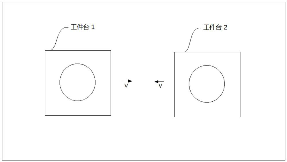
[0037] Such as figure 1 Shown is a schematic diagram of the main impact of two workpiece tables, driven by their respective drive units, the two workpiece tables move towards each other at a speed V on the working area to collide. Wherein, each workpiece table also includes a frame, the workpiece table is fixed on the frame, and the driving unit of the workpiece table drives the frame to drive the workpiece table to move, and figure 1 The drive unit and frame of the workpiece table are not shown in the figure.

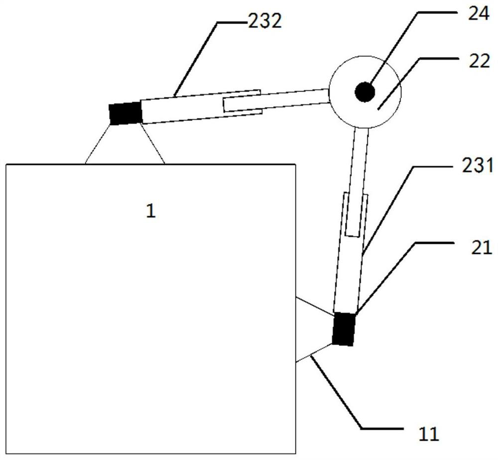
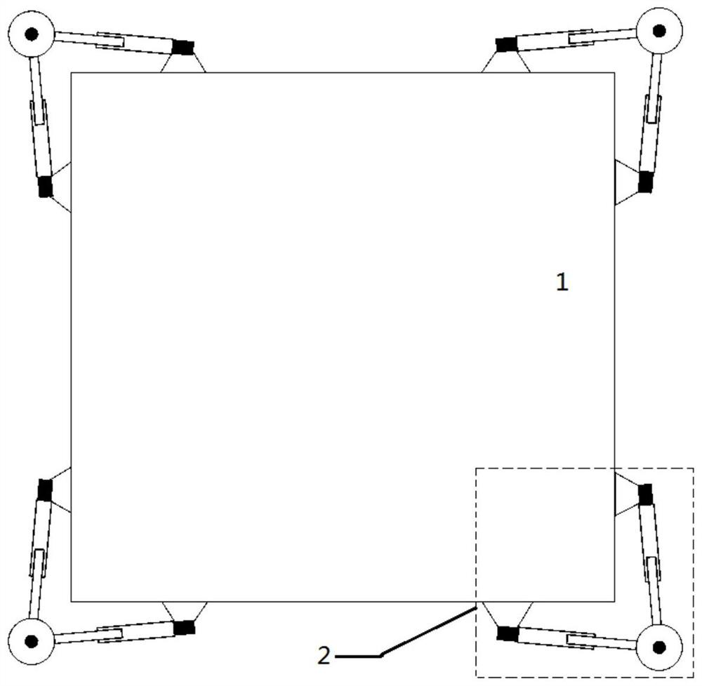
[0038] In order to protect the two workpiece tables, an anti-collision mechanism 2 is installed on the frame 1 of each workpiece table, such as figure 2 As shown, the anti-collision mechanism 2 is connected to the frame 1 of the workpiece table through two first hinges 21, and is used to protect the internal workpiece table components of the frame 1 from damage caused by the collision of the frame 1 in the movement plane. The frame 1 and the anti-collision mechanism...

Embodiment 2

[0054] In addition, considering that the collision between workpiece table systems may occur in addition to the collision situation in the first embodiment, such as Figure 6 In the collision situation shown, in order to make the anti-collision device cope with this special situation (if it is tested, it does exist), the structure of the anti-collision device in Embodiment 1 is improved, and a rectangular ring 25 is added. At the same time, the two buffer structures 231 and 232 can also be replaced with bi-directional buffers of other brands (not ACE brand).

[0055] Specifically, see Figure 7 , the anti-collision mechanism 2 includes a roller 22 and two buffer structures: a first buffer structure 231 or a second buffer structure 232, the roller 22 is connected to one end of the two buffer structures 231, 232 respectively through a second hinge 24, and the two buffer structures The other ends of the structures 231 and 232 are respectively connected with a first hinge 21 .

...

Embodiment 3

[0062] In addition, considering that the structure of the anti-collision mechanism 2 in the first and second embodiments may have vertical (Z direction) stability problems, the anti-collision mechanism 2 is further improved by adding a vertical stability module.

[0063] Specifically, see Figure 8 The anti-collision mechanism 2 includes a roller 22 and two buffer structures: a first buffer structure 231 or a second buffer structure 232, the roller 22 is connected with one end of the buffer structures 231, 232 through the second hinge 24, and the other end of the buffer structures 231, 232 One end is connected with a first hinge 21 respectively. The anti-collision mechanism 2 also includes a rectangular ring 25 fixed in the rollers 22 through grooves provided in the four rollers 22 .

[0064] In particular, the anti-collision mechanism 2 further includes a vertical stabilization module 26 disposed between the frame 1 and the buffer structures 231 , 232 . Wherein, the vertica...


PUM


Abstract

The invention discloses an anti-collision device, which comprises a frame, a first buffer structure, a second buffer structure and a connecting component. One end of the first buffer structure and oneend of the second buffer structure are rotationally connected at an acute angle through the connecting component, and the other end of the first buffer structure and the other end of the second buffer structure are arranged on the frame. According to the anti-collision device of the invention, an impact force in any direction applied under the guide of the connecting component is converted into the vertical forces of the two buffer structures through the two buffer structures rotationally connected at an acute angle at one end through the connecting component, and the problem that the traditional one-dimensional oil pressure buffer or memory alloy anti-collision bar can only prevent collision in one direction is solved. The anti-collision device has a simple structure layout, and is veryconvenient to install and debug and lighter. The anti-collision device does not occupy vertical space. When the anti-collision device is applied to a work piece stage system, a lot of space can be saved, and subsequent upgrade and improvement of the work piece stage system can be facilitated.

Description

technical field [0001] The invention relates to the technical field of photolithography, in particular to an anti-collision device, a workpiece platform system and a photolithography machine including the anti-collision device. Background technique [0002] Photolithography is a very important process in the semiconductor manufacturing process. It is a process of sequentially transferring chip patterns on a series of reticles to corresponding layers of silicon wafers through exposure. It is the core step in the manufacture of large-scale integrated circuits. A series of complex and time-consuming photolithography processes in semiconductor manufacturing are mainly completed by corresponding photolithography machines. [0003] The lithography machine includes multiple workpiece tables, and the position of each workpiece table needs to be adjusted during specific photolithography. Inevitably, the workpiece table of the lithography machine may collide in various situations dur...

Claims


Application Information

Patent Timeline
Patent Type & Authority Patents(China)
IPC IPC(8): G03F7/20
Inventor 管博然丛国栋李志龙张志钢刘屈武黄亚庆
Owner SHANGHAI MICRO ELECTRONICS EQUIP (GRP) CO LTD
Learn More