Hydraulic valve assembly with direction sliding valve and regeneration flow dividing valve with pressure compensation

A diverter valve, slide valve technology, applied in the field of hydraulic system, can solve problems such as affecting the efficiency of regeneration mode

Inactive Publication Date: 2009-03-18
HUSCO INT INC
View PDF5 Cites 14 Cited by
  • Summary
  • Abstract
  • Description
  • Claims
  • Application Information

AI Technical Summary

Problems solved by technology

However, energy losses in the hose between the valve assembly and the cylinder still affect the efficiency of regenerative mode

Method used


Image

  • Hydraulic valve assembly with direction sliding valve and regeneration flow dividing valve with pressure compensation
  • Hydraulic valve assembly with direction sliding valve and regeneration flow dividing valve with pressure compensation
  • Hydraulic valve assembly with direction sliding valve and regeneration flow dividing valve with pressure compensation

Examples


Embodiment Construction

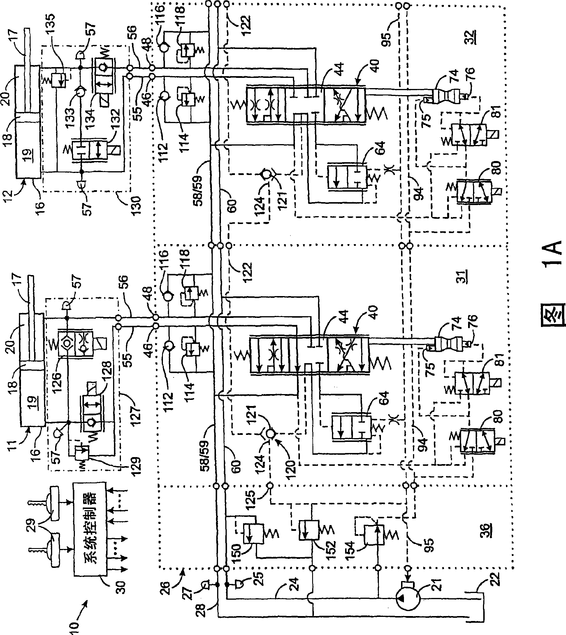
[0016] first reference figure 1 A and 1B, the hydraulic system 10 on the machine controls five hydraulic actuators 11 , 12, 13, 14 and 15 such as cylinder / piston assemblies. Each hydraulic actuator 11-15 comprises a hydraulic cylinder 16 with a movable piston 18 to which a piston rod 17 is connected. The piston 18 delimits a hydraulic head chamber 19 and a piston rod chamber 20 within the hydraulic cylinder, wherein first and second ports respectively hydraulically connected to these chambers are provided. It should be understood that other types of hydraulic actuators, such as rotary motors, may be used with the present invention.

[0017] The hydraulic system 10 also includes a variable displacement pump 21 that draws fluid from a tank 22 and provides fluid under pressure to a supply line 24 . The supply conduit is connected to a control valve assembly 26 which controls the flow of fluid to and from the hydraulic actuators 11-15. Fluid returning from the hydraulic actuato...


PUM


Abstract

The invention relates to a hydraulic valve component with a directional slide valve for pressure compensation and a regenerating shunt valve. According to the hydraulic valve component, a hydraulic loop controls fluid flow between a first port and a second port of a hydraulic actuator with a cylinder / piston structure and a feeding pipe and a reflowing pipeline of an oil tank. The hydraulic loop operates in a normal power operation mode and power and nonpower regeneration modes. Under the power operation mode, a traditional pressure compensation slide valve determines the speed of the hydraulic actuator. One working port of the slide valve is connected to the first port through a working port blocking valve; and the other working port is connected with the second port. The regenerating shunt valve is directly connected between the first port and the second port of the hydraulic loop. Under the regenerating operation mode or a power and regeneration mixing mode, the combination of the slide valve, the working port blocking valve and the regenerating shunt valve decides the speed of the hydraulic actuator.

Description

technical field [0001] The present invention relates to hydraulic systems for operating actuators such as cylinder / piston arrangements, and more particularly to hydraulic systems for operating actuators in power and regenerative modes. Background technique [0002] A large number of machines are operated by hydraulic systems with multiple hydraulic actuators, such as a cylinder connected to one part of the machine and a piston connected to another part by a piston rod. The piston divides the interior of the cylinder into two internal chambers, and alternating application of hydraulic fluid under pressure to each chamber moves the pistons in opposite directions, thereby moving the two components relative to each other. [0003] In common hydraulic systems, a manually operated valve controls the flow of hydraulic fluid to an air cylinder, wherein the operator moves a control rod mechanically connected to a spool located within the valve bore, as shown in US Patent No. 5,579,64...

Claims


Application Information

Patent Timeline
Patent Type & Authority Applications(China)
IPC IPC(8): F15B13/043F15B13/16
Inventor J·L·普法弗D·B·史蒂芬森
Owner HUSCO INT INC
Why Eureka
Try Eureka