Supercharge Your Innovation With Domain-Expert AI Agents!

Heater

A heater and resistor technology, applied in ohmic resistance heating, instruments, electric heating devices, etc., can solve the problem of reducing the pressure resistance of the protective film 95, and achieve the effect of increasing the pressure resistance and reducing the risk

Inactive Publication Date: 2009-03-18
ROHM CO LTD
View PDF1 Cites 4 Cited by
  • Summary
  • Abstract
  • Description
  • Claims
  • Application Information

AI Technical Summary

Problems solved by technology

The adverse effect is that the crack 95a can reduce the pressure resistance of the protective film 95

Method used


Image

  • Heater
  • Heater
  • Heater

Examples


Embodiment Construction

[0021] Preferred embodiments of the present invention will be described below with reference to the accompanying drawings.

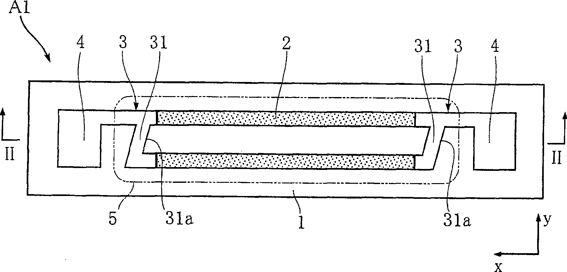
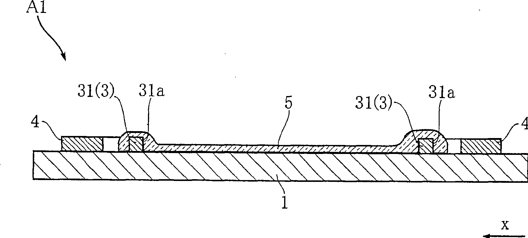
[0022] figure 1 and figure 2 A first embodiment of a heater according to the invention is shown. The heater A1 according to the present embodiment includes a substrate 1 , a resistor 2 , a wiring portion 3 , an electrode 4 and a protective film 5 . The heater A1 is used in a laser printer, for example, for heating recording paper to thermally fix the toner after the toner has been transferred onto the recording paper. It should be noted here that, for ease of understanding, the protective film 5 is drawn as figure 1 the imaginary line.

[0023] The substrate 1 is elongated and rectangular, and is made of insulating material. Examples of insulating materials include AlN and Al 2 o 3 .

[0024] The resistor 2 is formed on the substrate 1, and includes two strips in this embodiment. These strips extend in direction x, are parallel to each other ...


PUM


Abstract

A toner-fixing heater includes a substrate elongated in a first direction, a resistor formed on the substrate, a wiring portion connected with the resistor, and a protective film covering the resistor. The resistor includes two belt-like portions elongated in the first direction and spaced away from each other in a second direction perpendicular to the first direction. The resistor or the wiring portion includes a conductive portion for passing an electric current in the second direction. The conductive portion may have an edge extending in nonparallel to the first direction and the second direction, or may include a first layer and a second layer formed on the first layer, where the first layer is closer to the substrate than the second layer, and the edges of the second layer are located inward of the edges of the first layer as viewed in the first direction.

Description

technical field [0001] The present invention relates to a heater for heat-fixing toner transferred to recording paper incorporated, for example, in a laser printer. Background technique [0002] Conventionally, linear heaters are used in laser printers, for example, for heating recording paper to thermally fix transferred toner to the recording paper. An example of a conventional heater is disclosed in JP-A-2007-121955. [0003] For a better understanding of the present invention, the accompanying drawings Figure 8 and 9 A heater used as a reference example is shown. Specifically, the illustrated heater X includes a substrate 91 whose upper surface is formed with a pair of resistors 92 extending parallel to each other in the direction x. On the substrate 91 , a pair of electrodes are formed near each end of the extended substrate 92 . The electrode 92 is connected to a resistor 92 through a connection portion 93 . The connection portion 93 has a joint 93a extending in ...

Claims


Application Information

Patent Timeline
Patent Type & Authority Applications(China)
IPC IPC(8): G03G21/20H05B3/20
CPCH05B3/265
Inventor 有泷康之小畠忍佐古照久
Owner ROHM CO LTD
Features
  • R&D
  • Intellectual Property
  • Life Sciences
  • Materials
  • Tech Scout
  • Unparalleled Data Quality
  • Higher Quality Content
  • 60% Fewer Hallucinations
Learn More