Light-emitting material, light-emitting device, and electronic appliance
A technology of light-emitting devices and light-emitting materials, which is applied in the direction of light-emitting materials, electroluminescent light sources, chemical instruments and methods, etc., can solve the problems of difficult application of medium or small size, high power consumption of inorganic EL elements, etc., to achieve reduced power consumption, low Cost, Effect of High Light Emission Efficiency
- Summary
- Abstract
- Description
- Claims
- Application Information
AI Technical Summary
Problems solved by technology
Method used
Image
Examples
Embodiment approach 1
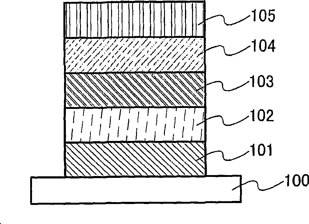
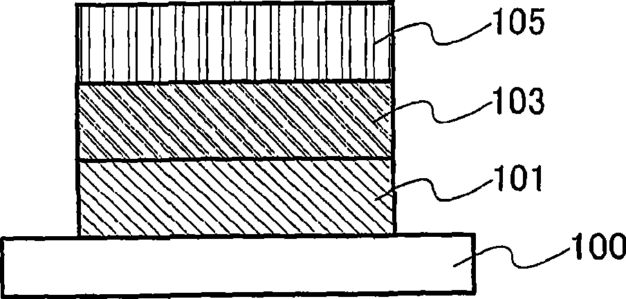
[0040] In this embodiment, reference will be made to Figure 1A and 1B The light-emitting element of the present invention is explained.
[0041] Such as Figure 1A As shown, the light-emitting element shown in this embodiment has an element structure in which the first electrode 101 and the second electrode 105 are provided on the substrate 100, and the first insulating layer 102 and the second insulating layer 104 are provided on the second between the first electrode 101 and the second electrode 105 , and the light emitting layer 103 is disposed between the first insulating layer 102 and the second insulating layer 104 . It will be noted that the first insulating layer 102 and the second insulating layer 104 are not necessary, and one of them may be omitted or as Figure 1B Both can be omitted as shown.
[0042] The substrate 100 serves as a support for the light emitting element. For example, glass, quartz, plastic, etc. may be used to form the substrate 100 . In addit...
Embodiment approach 2
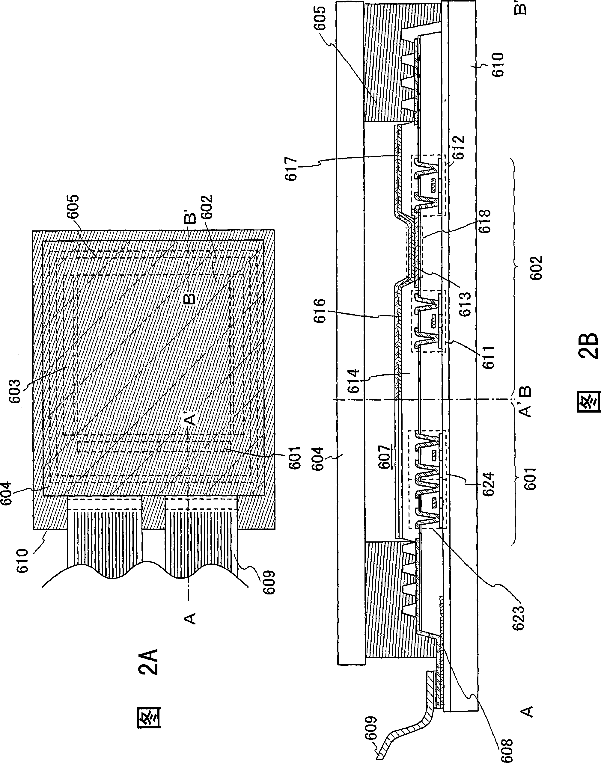
[0060] In this embodiment mode, a light emitting device having the light emitting element of the present invention will be explained.
[0061] In this embodiment mode, an active light emitting device in which driving of a light emitting element is controlled by a transistor will be explained. In this embodiment mode, a light emitting device using the light emitting element of the present invention for a pixel portion will be explained with reference to FIGS. 2A and 2B . It will be noted that FIG. 2A is a top view showing the light emitting device, and FIG. 2B is a cross-sectional view taken along lines A-A' and B-B' of FIG. 2A. Reference numeral 601 denotes a driver circuit section (source side driver circuit), 602 denotes a pixel section, and 603 denotes a driver circuit section (gate side driver circuit section), each indicated by a dotted line. Also, reference numeral 604 denotes a sealing substrate and 605 denotes a sealant, and a portion surrounded by these and the subst...
Embodiment approach 3
[0075] In this embodiment mode, a light emitting device having the light emitting element of the present invention will be explained with reference to FIG. 3 .
[0076] The light emitting device shown in this embodiment is a passive type light emitting device in which a light emitting element is driven in a pixel portion without particularly providing a driving element such as a transistor. FIG. 3 shows a perspective view of a passive light emitting device to which the present invention is applied. In addition, the light emitting device may be driven by DC driving or AC driving.
[0077] In FIG. 3 , on a substrate 951 , a layer 955 containing a luminescent material is disposed between a first electrode 952 and a second electrode 956 . Furthermore, the luminescent material according to the invention contained in the layer 955 has at least a luminescent substance, a matrix material and an additive. As an additive, an element belonging to Group 14 of the periodic table or a com...
PUM
| Property | Measurement | Unit |
|---|---|---|
| thickness | aaaaa | aaaaa |
| thickness | aaaaa | aaaaa |
| thickness | aaaaa | aaaaa |
Abstract
Description
Claims
Application Information
 - R&D
- Intellectual Property
- Life Sciences
- Materials
- Tech Scout
- Unparalleled Data Quality
- Higher Quality Content
- 60% Fewer Hallucinations
Browse by: Latest US Patents, China's latest patents, Technical Efficacy Thesaurus, Application Domain, Technology Topic, Popular Technical Reports.
© 2025 PatSnap. All rights reserved.Legal|Privacy policy|Modern Slavery Act Transparency Statement|Sitemap|About US| Contact US: help@patsnap.com


