
motor

A rotor and space technology, applied in the field of motors driving inertial separators, can solve problems such as leakage and easy wear

Inactive Publication Date: 2011-11-30
MAHLE INT GMBH
View PDF0 Cites 0 Cited by
  • Summary
  • Abstract
  • Description
  • Claims
  • Application Information

AI Technical Summary

Problems solved by technology

Such radial seals are expensive and tend to wear out during motor operation, making them likely to leak over time

Method used


Image

  • motor
  • motor

Examples


Embodiment Construction

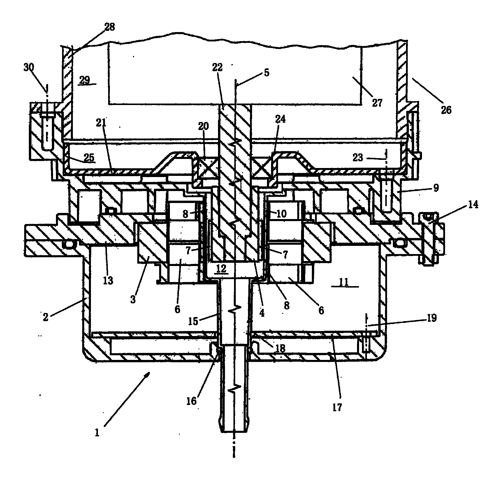
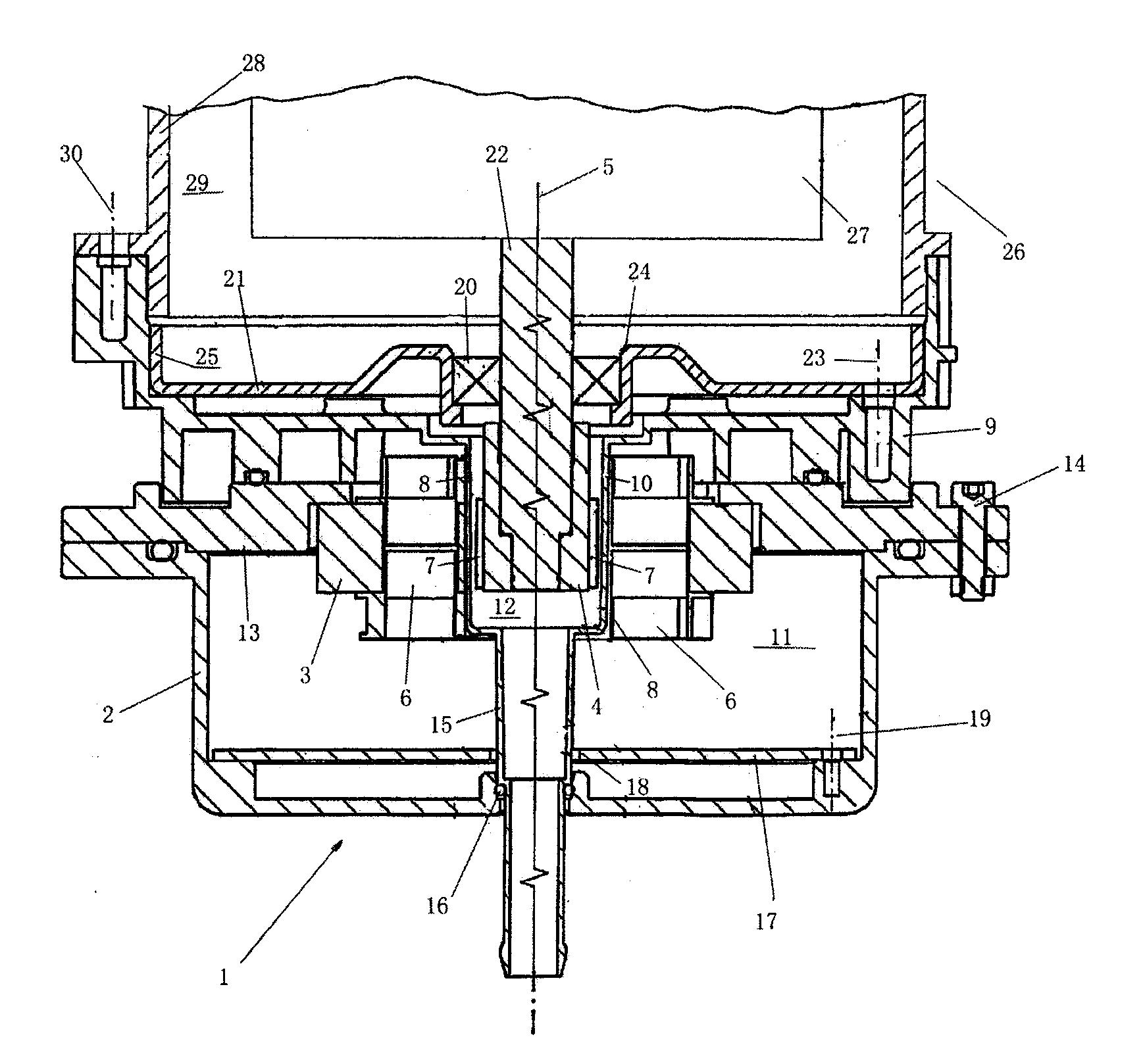
[0012] according to figure 1 , the inventive motor 1 comprises a stator housing 2 , a stator 3 disposed therein and a rotor 4 , wherein the rotor 4 is arranged coaxially with the stator 3 relative to the axis of rotation 5 . The motor 1 is designed as a brushless motor 1 . The stator 3 has at least one electromagnetic coil 6 for generating a magnetic field rotating about the axis of rotation 5 . The rotor 4 has at least one permanent magnet 7 which is able to transmit torque to the rotor 4 by means of electromagnetic force.

[0013] An annular gap 8 is formed radially between the rotor 4 and the stator 3 , which gap also extends coaxially with the axis of rotation 5 .

[0014] Furthermore, the electric machine 1 is equipped with a housing base 9 extending substantially through the axis of rotation 5 . The housing base 9 is designed and arranged relative to the other components of the electric machine 1 to extend through the annular gap 8 together with a non-magnetic part 10...


PUM


Abstract

An electric motor (1) for driving an inertial separator (26), comprising: a stator (3), arranged in a stator housing (2); a rotor (4), about an axis of rotation (5) and said A stator (3) is coaxially arranged and drivingly connected to a rotor (27) of said inertial separator (26). In order to seal the motor (1) more easily, a non-magnetic part (10) is extended from the bottom of the case (9), and the non-magnetic part (10) extends through the radially formed part between the rotor (4) and the stator (3) between the annular gap (8) such that it will accommodate the stator space (11) inside the stator housing (2) and the rotor space housing the rotor (4) (12) partitioned, wherein said rotor space (12) leads to a rotor space (29) housing said rotor (27) of said inertial separator (26).

Description

technical field [0001] The invention relates to an electric motor for driving an inertial separator. Background technique [0002] In particular applications, electric motors may be used to drive devices that are exposed to or operate with fluids. For example, an electric motor is used to drive a liquid pump or to drive a centrifuge or other inertial separator, for example, to separate residual oil in the exhaust line of an internal combustion engine. In this application, it is necessary to prevent corresponding liquids from penetrating into the interior of the motor. To this end, the motor must be provided with a sealed housing, and the shaft of the motor is designed to pass through with a sealed housing provided by radial seals. Such radial seals are expensive and tend to wear during motor operation, making them likely to leak over time. Contents of the invention [0003] The present invention relates to providing an improved embodiment of an electric machine, in part...

Claims


Application Information

Patent Timeline
Patent Type & Authority Patents(China)
IPC IPC(8): H02K5/128B04B9/04B04B7/04H02K5/167H02K7/14H02K7/16
CPCH02K7/14H02K5/1675H02K7/16B04B9/04H02K5/128
Inventor 克劳斯·贝茨
Owner MAHLE INT GMBH
Learn More