A rotating shaft lubrication device with automatic lubrication and more uniform application of lubricating fluid

A technology of automatic lubricating and lubricating device, applied in the direction of engine lubrication, lubricating parts, engine components, etc., can solve the problems of reducing the service life of the rotating shaft, increasing the maintenance cost, and the rotating shaft cannot be lubricated automatically, and achieves jet lubrication. The effect of uniform and improved work efficiency

Active Publication Date: 2022-01-04
临沂边锋自动化设备有限公司
View PDF6 Cites 0 Cited by
  • Summary
  • Abstract
  • Description
  • Claims
  • Application Information

AI Technical Summary

Problems solved by technology

[0005] Aiming at the deficiencies of the prior art, the present invention provides a rotating shaft lubricating device with automatic lubrication and more uniform application of lubricating fluid, which is capable of automatically lubricating when the surface of the rotating shaft is rusted and dry, and can be lubricated on the surface of the rotating shaft, and The spray lubrication is more uniform, and there is no need to lubricate after stopping the work, which improves the work efficiency and solves the problem that the shaft of the pick cannot be lubricated automatically, so that the friction on the shaft will increase when the pick is dry during work, reducing the friction. The service life of the rotating shaft is shortened, the maintenance cost is increased, and the equipment needs to be lubricated after stopping, which reduces the working efficiency

Method used


Image

  • A rotating shaft lubrication device with automatic lubrication and more uniform application of lubricating fluid
  • A rotating shaft lubrication device with automatic lubrication and more uniform application of lubricating fluid
  • A rotating shaft lubrication device with automatic lubrication and more uniform application of lubricating fluid

Examples


Embodiment Construction

[0026] The following will clearly and completely describe the technical solutions in the embodiments of the present invention with reference to the accompanying drawings in the embodiments of the present invention. Obviously, the described embodiments are only some, not all, embodiments of the present invention. Based on the embodiments of the present invention, all other embodiments obtained by persons of ordinary skill in the art without making creative efforts belong to the protection scope of the present invention.

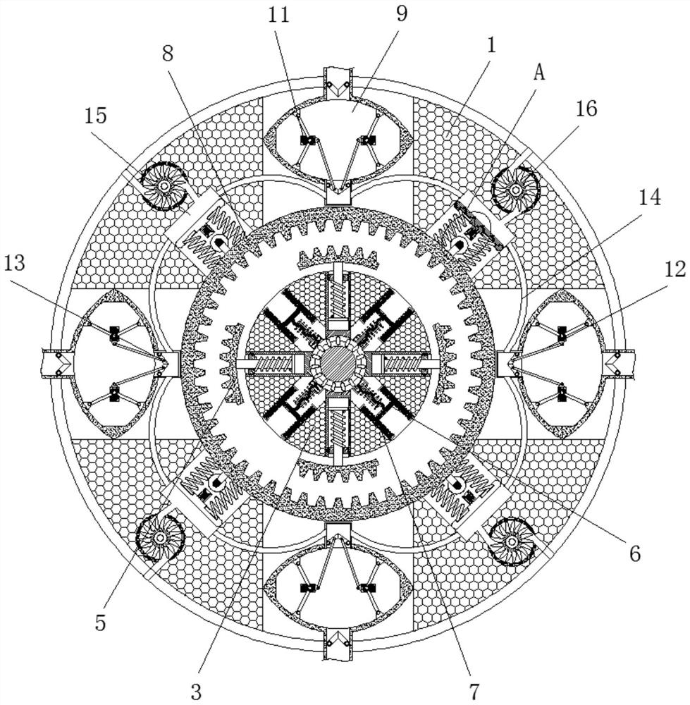
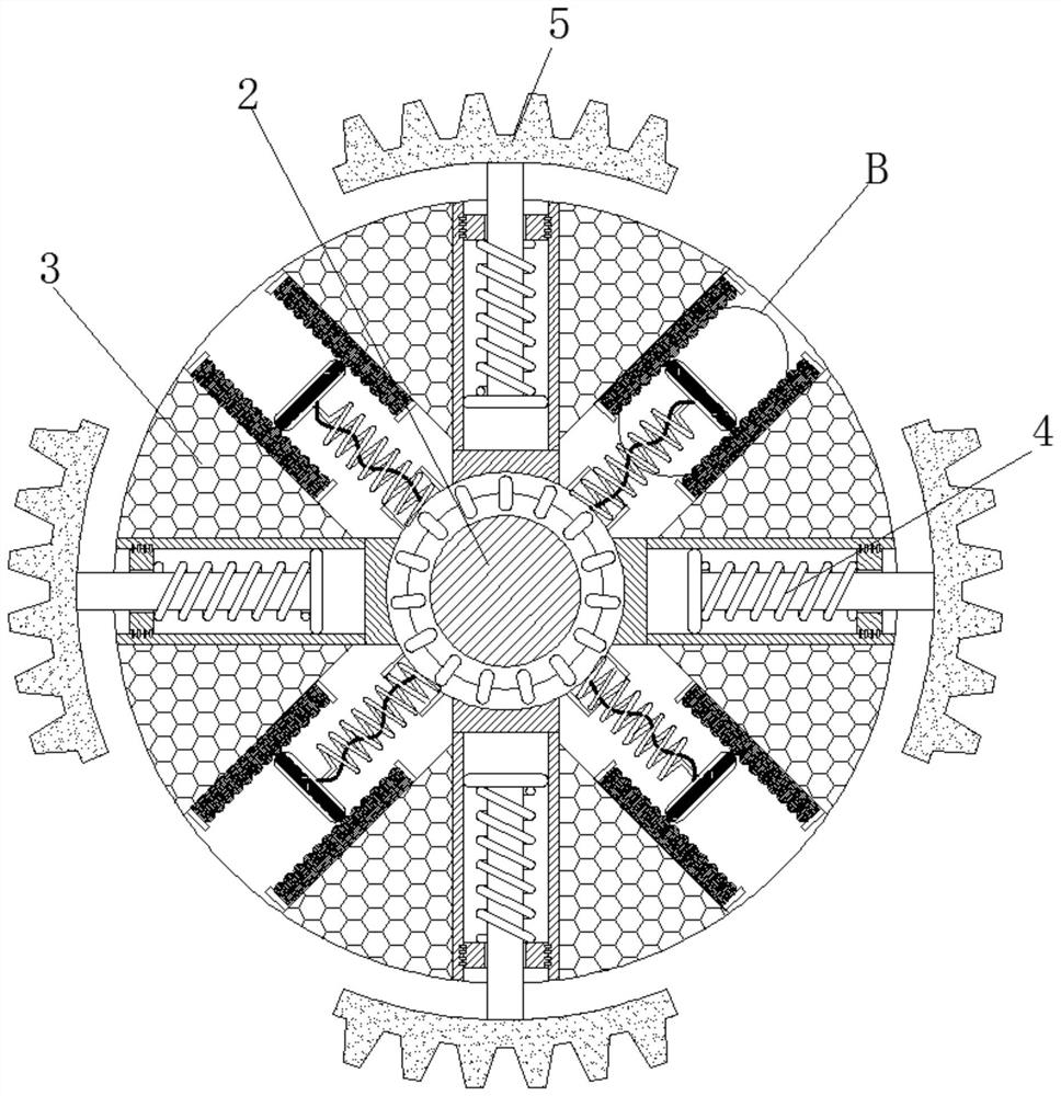
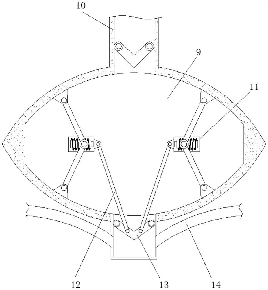
[0027] see Figure 1-6 , a rotating shaft lubricating device with automatic lubrication and more even application of lubricating fluid, comprising a mounting frame 1, a rotating shaft 2 is rotatably connected to the center of the mounting frame 1, and a pick is fixedly connected to the end of the rotating shaft 2 away from the mounting frame 1, and the rotating shaft 2 is connected to the servo The motor is fixedly connected, the surface of the rotating shaft ...


PUM


Abstract

The invention relates to the technical field of picks, and discloses a rotating shaft lubricating device with automatic lubrication and more even application of lubricating fluid, including a mounting frame, a rotating shaft is connected to the center of the mounting frame, and a mounting bracket is fixedly connected to the surface of the rotating shaft. The inside of the installation plate is slidably connected with a slide bar, the end of the slide bar is fixedly connected with a fixed block, the inside of the installation plate is slidably connected with a metal contact, and the side of the metal contact is slidably connected with a The resistance bar is fixedly connected with a transmission gear at the center of the circle inside the installation frame. Through the change of the mutual attraction between the electromagnetic rods, the attractive force between the electromagnetic rods increases when the speed is slow, the baffle can be opened and the internal lubricating fluid can be discharged, and the baffle can be closed when the speed is fast to stop lubrication, thus achieving In order to be able to automatically lubricate when the surface of the shaft is rusted and dry, and to prevent the effect of shaft wear due to insufficient lubrication during work.

Description

technical field [0001] The invention relates to the technical field of picks, in particular to a rotating shaft lubrication device with automatic lubrication and more uniform application of lubricating fluid. Background technique [0002] Picks are needed to break the soil during mineral collection and excavation, but now the shaft of the pick cannot be lubricated automatically, so that the friction on the shaft will increase when the pick is dry during work, reducing the use of the shaft The service life increases, the cost of maintenance is increased, and the equipment needs to be lubricated after stopping, which reduces the working efficiency. [0003] In order to solve the above problems, the inventor provided a rotating shaft lubrication device that automatically lubricates and applies the lubricating fluid more evenly. Through the change of the rotating shaft speed, the rotating speed of the mounting plate changes, and the mutual attraction between the electromagnetic ...

Claims


Application Information

Patent Timeline
Patent Type & Authority Patents(China)
IPC IPC(8): F16N7/02F16N7/00F16N21/00
CPCF16N7/02F16N7/00F16N21/00
Inventor 李长龙
Owner 临沂边锋自动化设备有限公司
Why Eureka
Try Eureka