Thermal forming of molded piece

A technology for thermoforming machines and parts, which is applied in the field of thermoforming of molded parts, and can solve problems such as difficulty in resetting, occupying floor space, and unsatisfactory

Inactive Publication Date: 2009-03-25
WAND PARKER IND
View PDF3 Cites 4 Cited by
  • Summary
  • Abstract
  • Description
  • Claims
  • Application Information

AI Technical Summary

Problems solved by technology

The disadvantage of this structure is that the punching machine has a separate drive and takes up additional floor area
This drive structure is subject to contact surface wear and tear, difficulty resetting the relative range of motion between the die and stripping element
[0016] All of the patents listed above have their own limitations and do not address the need for systems that improve thermoforming operations, especially the need for in-mold trimming of panels from formed parts to improve product quality and achieve higher production speeds

Method used


Image

  • Thermal forming of molded piece
  • Thermal forming of molded piece
  • Thermal forming of molded piece

Examples


Embodiment Construction

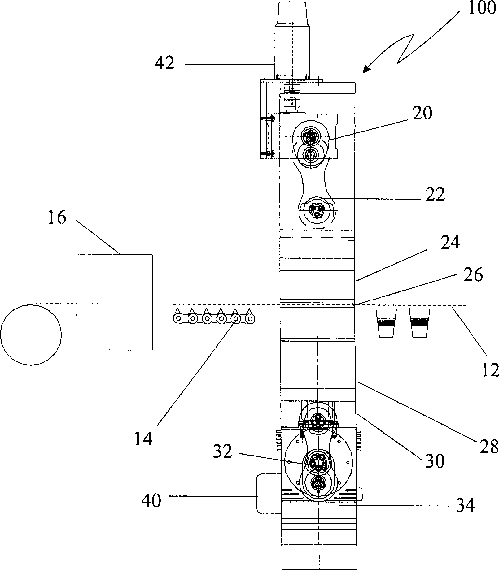
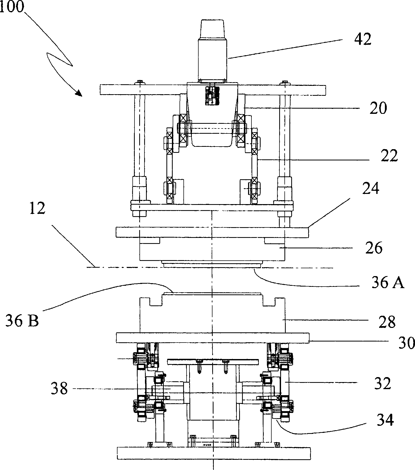
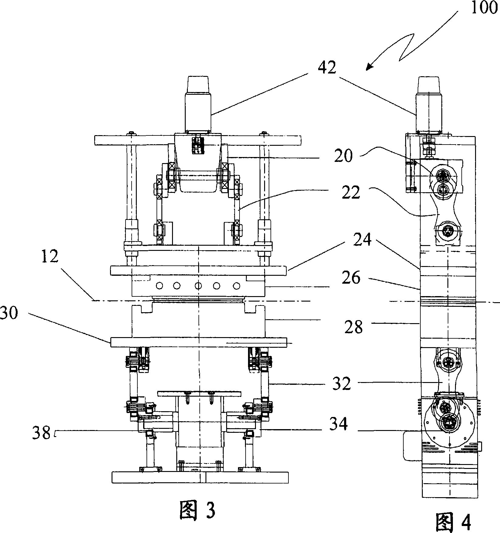
[0056] Referring to the drawings, a thermoforming machine according to the invention is indicated generally by the reference numeral 100 .

[0057] The machine includes a frame (not shown) in which an upper platen 24 and a lower platen 30 are disposed. A mold half 26 serving as a press-in male mold is mounted on the upper platen 24 . The other mold half 28 serving as a female mold part is mounted on the lower platen 30 . The upper pressing plate 24 is provided with a driving unit 42 , and the lower pressing plate is provided with a driving unit 40 . A connection mechanism in the form of a spline unit 20 and a link 22 is provided between the drive unit 42 and the upper platen 24 . Another connecting mechanism in the form of a spline unit 34 and a link 32 is provided between the drive unit 40 and the lower platen 30 . An in-mold cutting tool is provided in the machine 100 consisting of two parts 36A on the male press-in die part 26 and 36B on the female die part 28 .

[0058...


PUM


Abstract

The invention relates to a thermoforming machine which comprises a framework; a first pressure plate and a second pressure plate which are disposed on the framework at an interval; a male mould and a complementary female mould disposed on each pressure plate respectively; an in-mould cutting element with a complementary profile provided in the mould; two drive devices cooperating with each pressure plate and being used for moving the pressure plates to a first movement position for clamping plate material, a second movement position for stretching and forming the plate material, a third movement position for cutting the plate, and a fourth movement position for forming the mould-opening configuration; and a part for ejecting and forming from the mould cavity in the mould-opening configuration and a ejection device of the cut plate. The drive device comprises a prime motor; a spline unit connected to the prime motor; and a link rod positioned between the spline unit and each pressure plate to drive the movement.

Description

technical field [0001] The present invention relates to thermoforming of molded parts. [0002] In particular, the invention relates to high speed thermoforming machines. Background technique [0003] Thermoforming is one of the processes used to transform plastic resins into final products. Thermoforming is performed by pressure forming, vacuum forming and counter-molding. Thermoforming takes place by heating the thermoplastic sheet until it softens; the heating occurs immediately before the sheet is introduced into the forming machine. The sheet is then pressed onto the mold by pressure or vacuum until the part hardens. The formed part is then ejected from the mold and trimmed / trimmed to separate it from the plastic surround. [0004] Thermoforming equipment can range from simple furnaces and shaped molds to complex robotic machinery that transforms thermoplastic resin pellets into shaped parts at speeds unattainable by other methods. Thermoformable materials include ...

Claims


Application Information

Patent Timeline
Patent Type & Authority Applications(China)
IPC IPC(8): B29C51/18B29C51/32B29C51/44B29C51/08
Inventor S·A·拉西科拉B·M·纳拉炎劳M·R·孙达拉姆
Owner WAND PARKER IND
Why Eureka
Try Eureka