Control gate

A technology for controlling doors and channels, applied in the field of control doors, can solve the problems of low alternating magnetic field, increased time and cost, etc., and achieve the effects of reducing obstacles, improving work efficiency, and compact structure

A technology for controlling doors and channels, applied in the field of control doors, can solve the problems of low alternating magnetic field, increased time and cost, etc., and achieve the effects of reducing obstacles, improving work efficiency, and compact structure

CN101392618AInactive Publication Date: 2009-03-25FUJIFILM BUSINESS INNOVATION CORP

Image

  • Control gate
  • Control gate
  • Control gate

Examples


Embodiment Construction

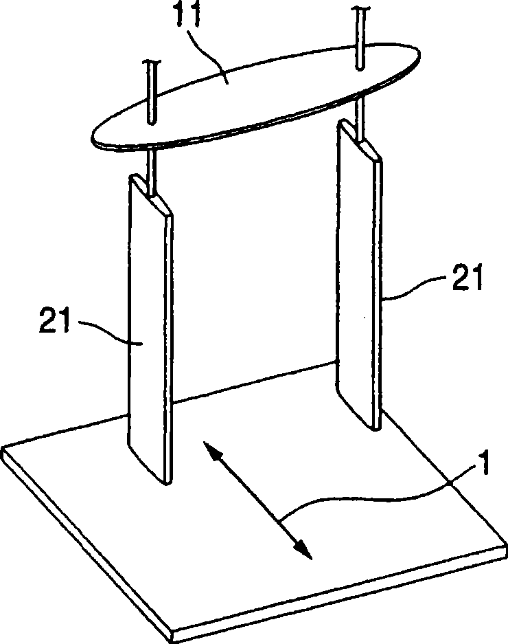
[0029] Now, various exemplary embodiments of the invention related to the present application will be described with reference to the accompanying drawings. Such as figure 1 The control gate shown is a gate for detecting confidential documents contained in carry-ons, and by installing this control gate at the entrance or exit of an area where secrecy must be ensured, it is possible to prevent confidential documents from being taken out or taken out illegally or by mistake enter.

[0030] In areas where confidentiality must be ensured, confidential matters are stored in the form of documents or electronic data, and documents are produced using printers or copiers. In this case, confidential documents are produced using paper containing a magnetic substance that produces the large Barkhausen effect. The paper may be such that the magnetic substances producing the large Barkhausen effect are embedded in the entire paper in a randomly dispersed manner and are not easily removed....


PUM


Abstract

A control gate, including an exciting coil and a detecting coil, is disclosed. The exciting coil forms an alternating magnetic field in a passageway at an entrance to or an exit from an area where taking out or bringing in of an object is controlled. The detecting coil detects a change of the magnetic field when magnetic substance contained in the object generating a large Barkhausen effect causes magnetic inversion in the alternating magnetic field. The exciting coil is provided above the passageway and has a winding wire wound along a horizontal plane. The detecting coil is provided in a side part of the passageway and has a winding wire wound along a vertical plane which is parallel to a passing direction of the passageway.

Description

technical field [0001] The present invention relates to a control gate that controls carried items that are prohibited from being taken out or brought into a specific area by detecting a change in a magnetic field due to magnetization reversal of a magnetic substance that produces a large Barkhausen effect. Background technique [0002] As a control gate for detecting the passage of a carry-on that is prohibited from being taken out or brought in and issuing an alarm, there is known a control gate using a magnetic substance that produces a large Barkhausen effect. [0003] For example, Patent Document 1 (JP-A-2003-182847) discloses a control gate in which a magnetic substance is added in advance to an object controlled to be taken out or brought into a controlled area, and when entering or leaving the The passage of the magnetic substance is detected in the channel of the control area, thereby controlling the carried objects. [0004] When a magnetic field larger than the c...

Claims


Application Information

Patent Timeline
25 Mar 2009
Publication
CN101392618A
IPC
E05F15/20; G01V3/10
CPC
E05G5/003
Inventors
高桥邦广; 马里奥·福斯