Expansion bolt

A technology of expansion bolts and expansion tubes, applied in the direction of connecting components, pins, mechanical equipment, etc., can solve the problems affecting the appearance, etc., and achieve fast fixing speed, high firmness, and good stress effect

Inactive Publication Date: 2009-03-25
HUBEI WENBANG PLASTICS
View PDF1 Cites 11 Cited by
  • Summary
  • Abstract
  • Description
  • Claims
  • Application Information

AI Technical Summary

Problems solved by technology

Since the screw rod moves upward relatively (relative to the expansion tube), after the expansion bolt is fixed, the screw rod protrudes from the fixed body for a long time, which becomes an obstacle and also affects the appearance

Method used


Image

  • Expansion bolt
  • Expansion bolt
  • Expansion bolt

Examples


Embodiment 1

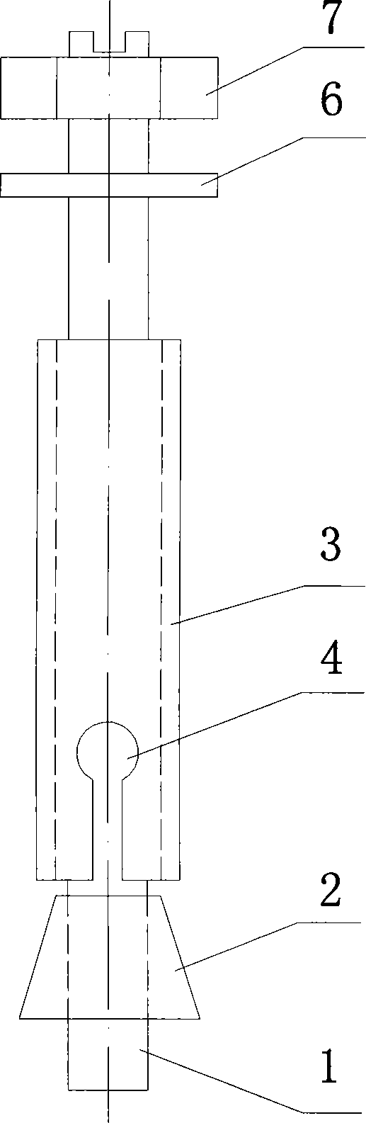
[0016] like figure 1 As shown, the expansion bolt includes a screw rod 1, a lower tapered nut 2, an expansion tube 3, a washer 6, and a nut 7. The lower end of the expansion tube 3 is provided with an equally divided opening groove 4, and the screw rod 1 is provided with an external thread , the lower end of the screw 1 passes through the expansion tube 3; the upper end of the screw 1 is welded with a nut 7 (the nut 7 and the screw 1 can also be an integral structure), and the nut 7 is located above the expansion tube 3; the screw 1 is covered with The washer 6, the washer 6 is located above the expansion tube 3; the lower end of the screw 1 is screwed with a lower conical nut 2, the lower conical nut 2 is located below the expansion tube 3, the small end of the lower conical nut 2 faces upwards, and the lower end of the lower conical nut 2 faces upwards. The outer diameter of the small end of the conical nut 2 is less than or equal to the inner diameter of the expansion tube ...

Embodiment 2

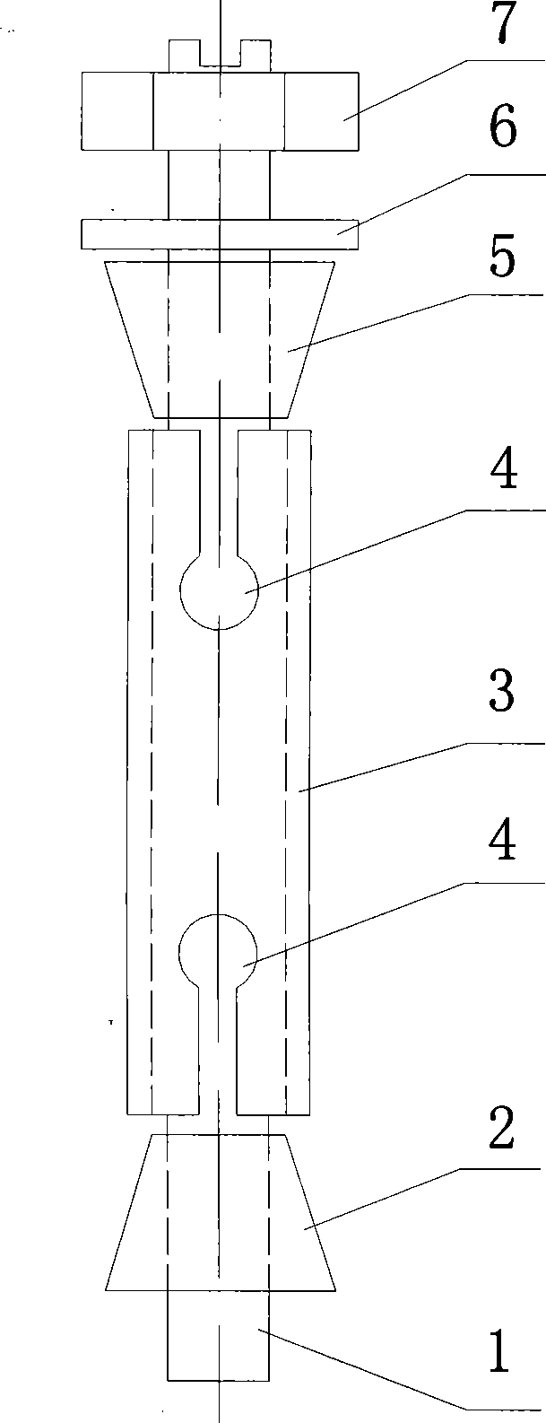
[0018] like figure 2 As shown, the expansion bolt includes a screw rod 1, a lower conical nut 2, an expansion tube 3, an upper conical nut 5, a washer 6, and a nut 7; both ends of the expansion tube 3 are provided with equally divided opening grooves 4 The upper and lower parts of the screw rod 1 are respectively provided with external threads, and the lower external threads of the screw rod 1 are opposite to the upper external threads; the screw rod 1 is covered with a gasket 6, and the gasket 6 is located above the expansion tube 3; the upper part of the screw rod 1 is screwed with an upper Conical nut 5, the upper conical nut 5 is located between the washer 6 and the expansion tube 3 (the upper conical nut 5 is located above the expansion tube 3), and the upper end of the screw rod 1 is welded with a nut 7 (the nut 7 and the screw rod 1 are also Can be an integral structure), the nut 7 is positioned above the expansion tube 3; the small end of the upper tapered nut 5 faces...

Embodiment 3

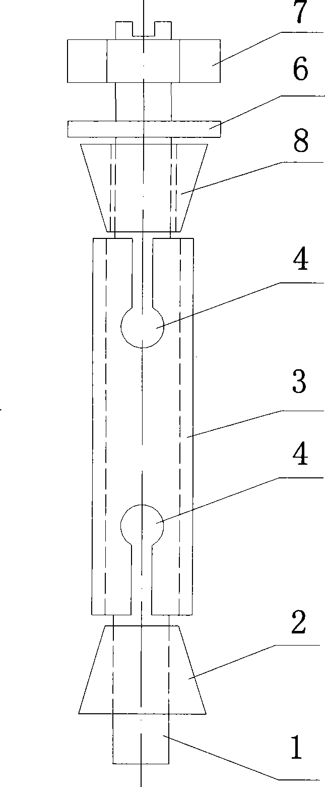
[0020] like image 3 As shown, it is basically the same as Embodiment 1, the difference is that: the screw rod 1 is covered with an upper cone body 8, the upper cone body 8 is provided with a screw through hole, and the screw rod 1 passes through the screw rod of the upper cone body 8 Through hole, the upper cone 8 is located above the expansion tube 3; the upper end of the expansion tube 3 is provided with equally divided opening grooves; the small end of the upper cone 8 faces downward, and the outer diameter of the small end of the upper cone 8 is less than Or equal to the inner diameter of the expansion tube 3, the outer diameter of the big end of the upper cone 8 is greater than the inner diameter of the expansion tube 3. When rotating, the nut 7 presses the upper cone 8 into the expansion tube 3 .


PUM


Abstract

The invention relates to an expansion bolt, which comprises a threaded rod and an expansion tube, wherein the lower end part of the expansion tube is provided with equant open slots, the threaded rod is provided with outside threads, and the lower end part of the threaded rod passes through the expansion tube. The expansion bolt is characterized in that a screw cap is welded on the upper end of the threaded rod and is positioned on the expansion tube; a lower tapered nut is screwed on the lower end part of the threaded rod and is positioned under the expansion tube, the small head end of the lower tapered nut faces upwards, the outer diameter of the small head end of the lower tapered nut is less than or equal to the inner diameter of the expansion tube, and the outer diameter of the big head end of the lower tapered nut is larger than the inner diameter of the expansion tube. When the expansion bolt is used, the threaded rod is exposed little and the expansion bolt is beautiful.

Description

technical field [0001] The invention relates to an expansion bolt. Background technique [0002] Present expansion bolts, such as Chinese patent application number: 200610038227.0 (powerful expansion bolts), etc., all adopt nuts that rotate on the screw rod, and the screw rod moves upward relatively (moves outward), and the nut moves on the screw rod to compress the conical cap. The conical cap fixed on the screw rod is squeezed to the expansion tube to realize expansion and fixation. Because the screw rod moves upwards relatively (relative to the expansion tube), after the expansion bolt is fixed, the screw rod is exposed to the fixed body for a long time, which becomes a kind of obstacle and also affects the appearance. Contents of the invention [0003] The purpose of the present invention is to provide an expansion bolt. After the expansion bolt is used, the screw rod is less exposed, and the expansion bolt is beautiful. [0004] In order to achieve the above object,...

Claims


Application Information

Patent Timeline
Patent Type & Authority Applications(China)
IPC IPC(8): F16B13/06
Inventor 聂家华杨永胜朱红卫刘杰孙麟
Owner HUBEI WENBANG PLASTICS
Why Eureka
Try Eureka