Magnetic powder inspection apparatus

A magnetic particle flaw detection and current coil technology, applied in the direction of material magnetic variables, etc., can solve the problems of poor consistency of manual winding, unsuitable batch testing, cumbersome manual winding, etc., to achieve good and reliable contact, increased flexibility, and uniform magnetic field distribution.

Active Publication Date: 2009-03-25
盐城东车科技有限公司
View PDF0 Cites 6 Cited by
  • Summary
  • Abstract
  • Description
  • Claims
  • Application Information

AI Technical Summary

Problems solved by technology

Its disadvantage is that manual winding is cumbersome, and the consistency of manual winding is poor, the work efficiency is low, and it is not suitable for batch detection

Method used


Image

  • Magnetic powder inspection apparatus
  • Magnetic powder inspection apparatus
  • Magnetic powder inspection apparatus

Examples


Embodiment 1

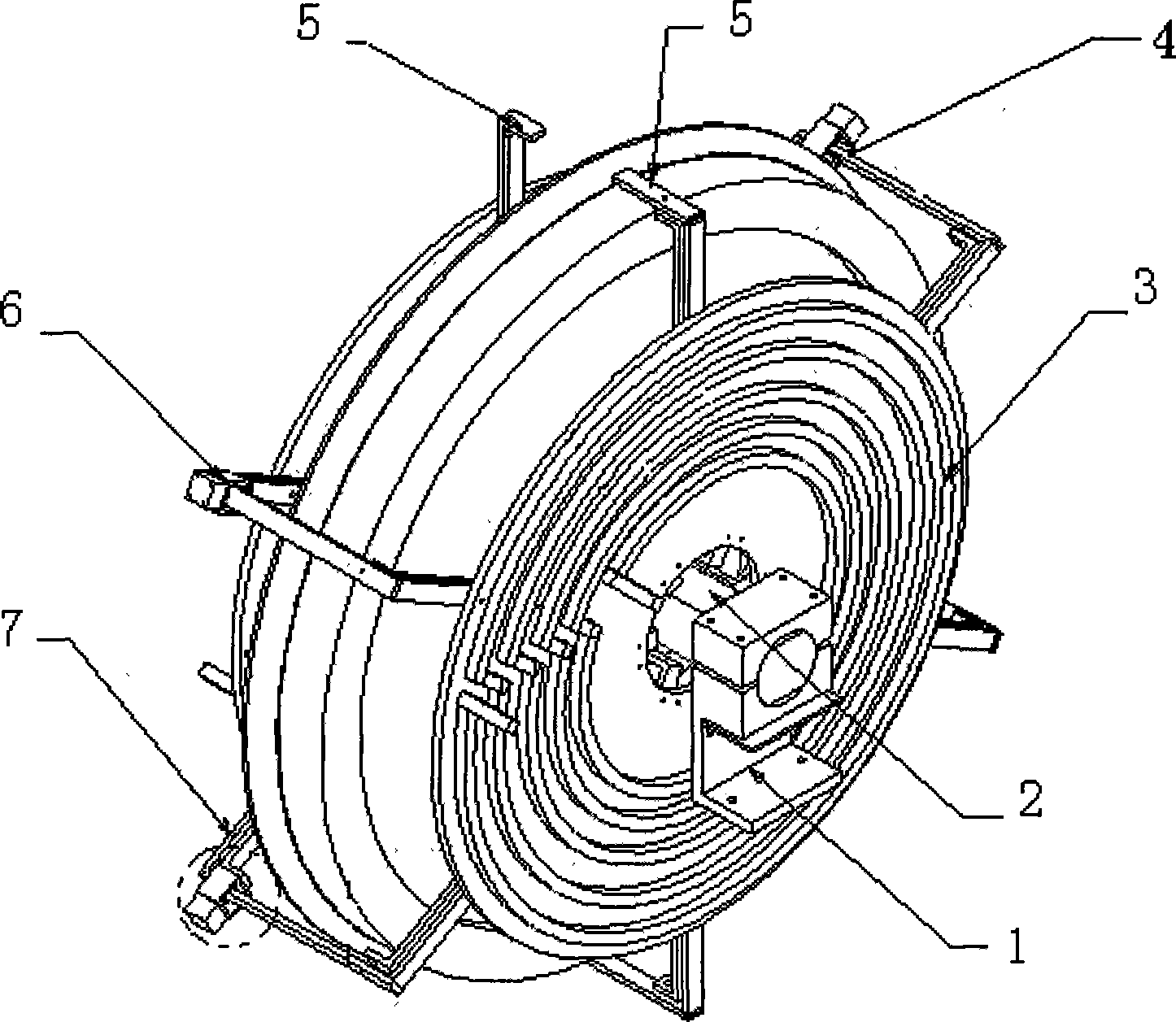
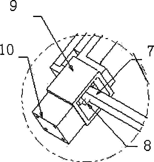
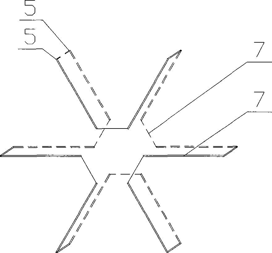
[0029] like figure 1 As shown, the workpiece to be detected is a ring workpiece with a diameter of 1250mm, a thickness of 210mm and an inner hole of 230mm, such as a locomotive wheel, wheel center and other ring workpieces. The made fork-shaped current coil 7 is in the shape of a fork, and each turn is projected as a U-shape. , the epoxy resin board is connected with the movable mechanism of the flaw detection device through the fixed seat 1, which not only plays the role of fixing but also plays the role of inter-turn insulation. The toroidal current coil 3 and the iron core detection magnet bar 2 are also fixed on the fixing base 1 . The fork-shaped current coils 7 on the left and right sides are connected through the connecting terminals 4 at the outer diameter surface of the workpiece to be detected. The mouth-shaped bracket 9 is equipped with a left fork-shaped coil fork tip, the fork tip is an inclined surface contact piece, and a compression plate 8 is also installed ...

Embodiment 2

[0031] The detected workpiece is an extra-large annular workpiece with a diameter of 2530mm, a thickness of 110mm, and an inner hole of 1850mm, such as annular workpieces such as the inner and outer rings of the pitch bearing. The fork-shaped current coil is in the shape of a fork, and each turn is projected as a U-shape. It is connected with the movable mechanism of the flaw detection device through the fixed base 1 . The length of the fork arm of the fork-shaped current coil is 80mm, the length of the fork-back rod is 850mm, the length of the fork arm of the right fork-shaped coil is 450mm, and the length of the fork-back rod is 1350mm. There are 15 mouth-shaped contacts at the fork-tip contact of the left fork-shaped coil. The bracket adopts a total of 15 small cylinders to drive the meshing and pressing mechanism to mesh, and the angle between the coils is 45 degrees.

[0032] The present invention is applicable to the detection of other similar annular, disc or hollow work...


PUM

PropertyMeasurementUnit
diameteraaaaaaaaaa
thicknessaaaaaaaaaa

Abstract

The invention relates to a magnetic powder flaw detection device which comprises furcated current coils distributed on the positions of two end faces of a detected workpiece; the detected workpiece shows a two-surface surrounded shape by the furcated current coils; each furcated current coils in the positions of the end faces of the detected workpiece consist of a plurality of conductor wires which are radial from center to outside; the furcated current coils in the positions of the left end face and the right end face are fixed on two permanent seats of flaw detection equipment; two permanent seats can relatively move; the furcated current coils in the positions of the left end face and the right end face are connected through a wire connecting terminal which can be opened and closed; and when the wire connecting terminal is closed, the furcated current coils are connected to form a current passage. The magnetic powder flaw detection device overcomes the disadvantages of a rod-threading method in detecting a large-scale annular, disc or hollow workpiece, has an ideal magnetizing effect and an accurate and reliable detection result, and is suitable for batch detection, in particular for the detection of the annular, disc or hollow workpiece with large difference between inside diameter and outside diameter.

Description

technical field [0001] The invention relates to a magnetization device of a magnetic particle flaw detector, in particular to a magnetized coil of the magnetic particle flaw detector. Background technique [0002] Magnetic particle inspection uses magnetic phenomena to detect surface and near-surface defects of workpieces. It is one of the most commonly used magnetic flux leakage detection methods. The basis of magnetic particle inspection is the magnetic interaction between the leakage magnetic field at the defect and the magnetic particle. After the ferromagnetic material or workpiece is magnetized, the magnetic field lines are deformed at the defects on the surface and near the surface, escaping from the surface of the workpiece to form magnetic poles and form a detectable leakage magnetic field. At this time, sprinkle magnetic powder or pour magnetic suspension on the surface of the workpiece, and the magnetic powder particles will be adsorbed on the defect area, showin...

Claims


Application Information

Patent Timeline
Patent Type & Authority Applications(China)
IPC IPC(8): G01N27/84
Inventor 杨晓春沈育辉
Owner 盐城东车科技有限公司
Why Eureka
Try Eureka