A high-power jump-type thermostat and its assembly method
A jump-type thermostat, high-power technology, applied in the direction of electrical components, electrical switches, circuits, etc., can solve problems such as poor contact, small conductive cross-sectional area, etc., to improve service life, reliable work, and improve electrical connection reliability sexual effect
- Summary
- Abstract
- Description
- Claims
- Application Information
AI Technical Summary
Problems solved by technology
Method used
Image
Examples
Embodiment 1
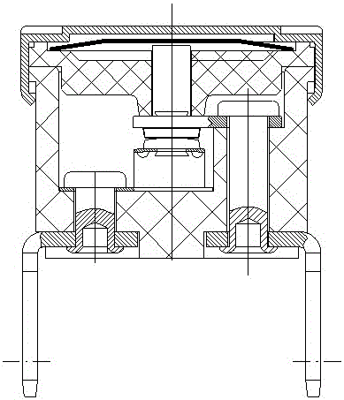
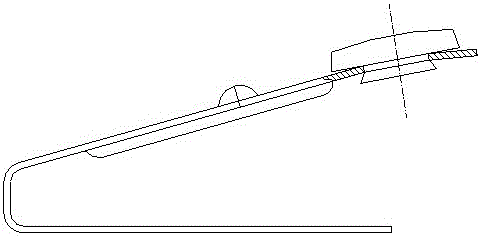
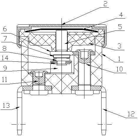
[0022] Such as image 3 , 4 , 5, the jump-type thermostat of this embodiment includes a housing 1, a cover 2, a guide frame 3, a bimetal disc 4, an action rod 5, a fixed plate 6, and a static contact 7. The static contact piece, the movable contact assembly composed of the movable contact 8 and the shrapnel 9, the first rivet 10, the second rivet 11, the first terminal 12, the second terminal 13, the action rod 5 is installed on the guide frame 3, the end of the action rod 5 faces the shrapnel 9; the bimetal disc 4 is located between the cover 2 and the action rod 5; On the inner and outer sides of the housing 1 , the elastic piece 9 and the second connection terminal 13 in the movable contact assembly are pressed against the inner and outer sides of the housing 1 by the second rivets 11 .
[0023] The above-mentioned assembly method of the jump-type thermostat includes the steps of assembling the movable contact assembly, installing the static contact piece and the first te...
Embodiment 2
[0027] Such as Image 6 As shown, the shrapnel 9 in this embodiment is provided with a nail hole, the handle of the movable contact 8 is a hollow handle, and the handle of the movable contact 8 is riveted with the shrapnel 9 after passing through the nail hole. The shank of 8 forms an annular pressing surface that is pressed against the shrapnel 9 .
[0028] The above steps of assembling the moving contact assembly are as follows: use the moving contact 8 with a hollow handle, pass the handle of the moving contact 8 through the nail hole and rivet it with the shrapnel 9, so that the handle of the moving contact 8 expands and flangs, and then connects with the The nail hole of the elastic piece 9 is interference fit, and makes the handle of the movable contact 8 form an annular pressing surface pressed against the elastic piece 9 .
[0029] Other structures and assembly methods of this embodiment are the same as those of Embodiment 1, and will not be repeated here.
Embodiment 3
[0031] Such as Figure 7 As shown, the shrapnel 9 in this embodiment is provided with a nail hole, and the handle of the movable contact 8 is provided with an axial groove, and the handle of the movable contact 8 passes through the nail hole and is riveted with the shrapnel 9. The flanging of the handle of the contact 8 forms a pressing surface that is pressed against the elastic piece 9 .
[0032] The above steps of assembling the moving contact assembly are as follows: use the moving contact 8 with an axial groove on the handle, pass the handle of the moving contact 8 through the nail hole and rivet it with the shrapnel 9, so that the handle of the moving contact 8 expands Afterwards, the two sides are separated, and are interference-fitted with the nail holes of the elastic piece 9 , and the handle of the movable contact 8 forms a pressing surface pressed against the elastic piece 9 .
[0033] Other structures and assembly methods of this embodiment are the same as those o...
PUM
 Abstract
Description
Claims
Application Information
 - R&D
- Intellectual Property
- Life Sciences
- Materials
- Tech Scout
- Unparalleled Data Quality
- Higher Quality Content
- 60% Fewer Hallucinations
Browse by: Latest US Patents, China's latest patents, Technical Efficacy Thesaurus, Application Domain, Technology Topic, Popular Technical Reports.
© 2025 PatSnap. All rights reserved.Legal|Privacy policy|Modern Slavery Act Transparency Statement|Sitemap|About US| Contact US: help@patsnap.com


