Fluorescent flat optical waveguide solar cell photovoltaic power generation system

A photovoltaic power generation system and planar optical waveguide technology, which is applied in photovoltaic power generation, circuits, electrical components, etc., can solve problems such as high cost and reduced efficiency, and achieve the effects of reducing consumption, large equivalent light concentration, and reducing costs

Inactive Publication Date: 2009-03-25
UNIV OF SCI & TECH OF CHINA
View PDF0 Cites 9 Cited by
  • Summary
  • Abstract
  • Description
  • Claims
  • Application Information

AI Technical Summary

Benefits of technology

This technology helps focus more energy onto smaller areas inside an optoeletronic device by converting visible lights into invisible ones for better image quality or generating electricity from heated surfaces instead of relying solely upon expensive materials like silicon (Si). By focusing this light towards one area at once rather than collect it multiple times over time, fewer costs are saved compared to traditional methods such as lenses used alone.

Problems solved by technology

This patents discusses different methods used during manufacturing or developing new materials with improved performance compared to traditional silicon based devices due to their low costs and potential benefits from sustainability concerns over future generations. However, there may still exist technical problem areas where current technologies cannot meet these goals effectively without sacrificial land usage.

Method used


Image

  • Fluorescent flat optical waveguide solar cell photovoltaic power generation system
  • Fluorescent flat optical waveguide solar cell photovoltaic power generation system
  • Fluorescent flat optical waveguide solar cell photovoltaic power generation system

Examples


Embodiment 1

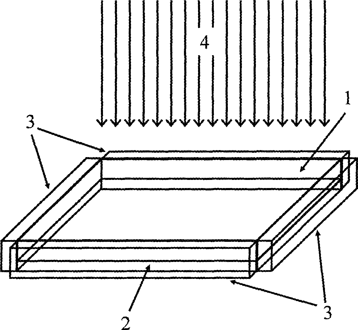
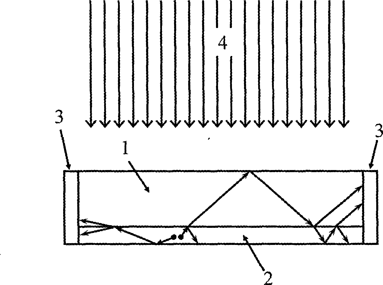
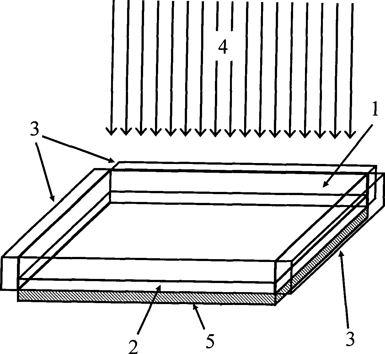
[0045] see figure 1 , image 3 and Figure 5 , 5wt% rare earth co-luminescence organic complex (Eu 0.05 , La 0.4 )(DBM) 3 Phen (rare earth dibenzoylmethane o-phenanthroline complex) mixed with polymethyl methacrylate (PMMA) matrix, spin-coated on ordinary glass 1 with a thickness of 3 mm, a length of 1.5 m and a width of 0.5 m to form a 10 micron Thick fluorescent material layer 2 . Aluminum (Al) reflective film 7 is coated on two 1.5m sides and one 0.5m side of glass 1, and silicon solar energy is bonded to the other 0.5m side with UV-3129 ultraviolet curing adhesive from Shenzhen Xinyi Adhesive Co., Ltd. battery3. The refractive index of ordinary glass and PMMA is about 1.5, and the numerical aperture of the corresponding planar optical waveguide is 0.75 (that is, 75% of the fluorescence enters the transmission mode). The fluorescent material absorbs sunlight in the 300nm-400nm band (ultraviolet part, accounting for about 5% of the total solar radiation), radiates flu...

Embodiment 2

[0052] see Figure 6 and Figure 7 , 5wt% rare earth co-luminescence organic complex (Eu 0.05 , Tb 0.1 )(DBM) 3 Phen (rare earth dibenzoylmethane phenanthroline complex) mixed with polymethyl methacrylate (PMMA) matrix, spin-coated on a polyethylene (PE) transparent sheet 1 with a thickness of 0.1 mm, a length of 1 m, and a width of 20 cm , forming a fluorescent material layer 2 with a thickness of 10 micrometers. The lower surface of the fluorescent material layer 2 is plated with an aluminum (Al) reflective film 5, and the upper surface of the transparent sheet 1 is provided with a high-efficiency light-transmitting, reflective (Eu 0.05 , Tb 0.1 )(DBM) 3 The photonic crystal 8 of Phen fluorescent wavelength, two 1m sides of transparent plate 1 and a 20cm side are coated with aluminum (Al) reflective film 7, and the other 20cm side uses the UV-3129 ultraviolet light of Shenzhen Xinyi Adhesive Industry Co., Ltd. Curing the adhesive to bond the gallium arsenide solar cel...

Embodiment 3

[0060] see Figure 4 , in order to further reduce the amount of solar cells, on the basis of Example 1, parallel concave-convex grooves 6 can be set on the surface of the fluorescent planar light guide, so that the fluorescence can only be transmitted to the two sides along the direction parallel to the concave-convex grooves 6, that is The solar cells 3 are only arranged on the two sides of the fluorescent planar light waveguide perpendicular to the concave-convex groove 6, thereby reducing the usage of the solar cells from four to two. Further, one of the two solar cells perpendicular to the concave-convex groove 6 can also be replaced with a side reflective film 7, such as Figure 4 Shown in 7. The side reflective film 7 reflects back the fluorescent light reaching this side and couples it into the solar cell from the other side.


PUM

PropertyMeasurementUnit
Thickness rangeaaaaaaaaaa
Thicknessaaaaaaaaaa
Surface areaaaaaaaaaaa

Abstract

The invention relates to a fluorescent planar optical wave guide solar-cell photovoltaic generation system, and aims to form the fluorescent planar optical wave guide solar-cell photovoltaic generation system by combining a fluorescent material, the planar optical wave guide technology and solar cells so as to reduce the cost of solar-cell photovoltaic generation. The system for the invention comprise a fluorescent planar optical wave guide and the solar cells; as a flake-shaped optical structure, the fluorescent planar optical wave guide is composed of a transparent medium layer and a fluorescent material layer; and the solar cells are arranged on side surfaces of the fluorescent planar optical wave guide through scotch tapes. The beneficial technical effect of the invention leads to the realization of using the solar cells arranged on the side surfaces to receive light supposed to arrive at the whole surfaces, thereby achieving great equivalent light concentration effects. The fact that the cost of the fluorescent planar optical wave guide is far less that that of the solar cells results in a heavy decrease in the quantity of the solar cells for use with the cost of the solar power photovoltaic generation greatly reduced.

Description


Claims


Application Information

Patent Timeline
Owner UNIV OF SCI & TECH OF CHINA
Why Eureka
Try Eureka