
Improved guide feeding device

A feeder, guide roller technology, applied in metal processing equipment, feeding devices, manufacturing tools, etc., can solve problems such as affecting the quality of the steel strip, the deviation of the steel strip, and insufficient traction.

Inactive Publication Date: 2009-04-01
肖荣
View PDF0 Cites 0 Cited by
  • Summary
  • Abstract
  • Description
  • Claims
  • Application Information

AI Technical Summary

Problems solved by technology

Since the steel strip coming down from the unwinder is not smooth enough, it also has the function of leveling when passing through the feeder. The contact area between the leveled steel strip and the driving roller and driven roller is reduced, and the driving roller and driven roller The friction between the moving roller and the steel belt is reduced, so that the steel belt, especially the thick steel belt, is not sufficiently drawn, and the belt is prone to immobility, and the conveyed steel belt is likely to be deflected due to insufficient traction. This will affect the quality of the steel strip

Method used


Image

  • Improved guide feeding device
  • Improved guide feeding device

Examples


Embodiment Construction

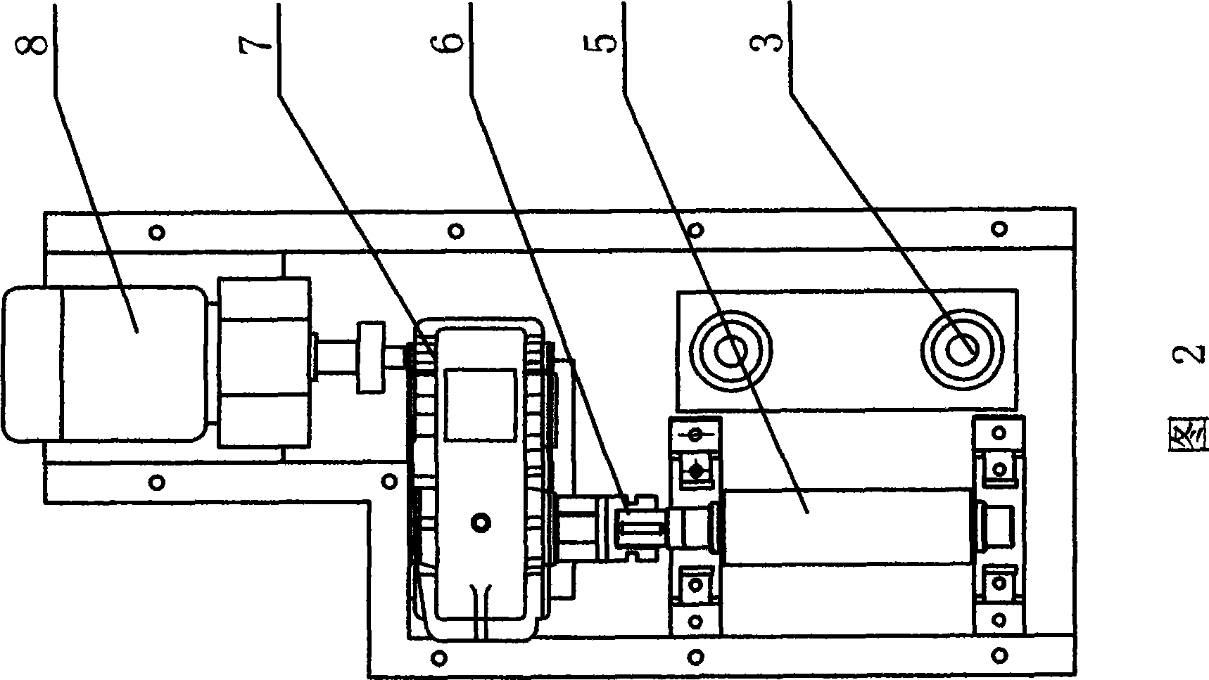
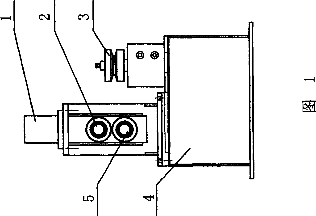
[0009] See Fig. 1, Fig. 2, the present invention comprises motor 8, speed reducer 7, driving roller 5, driven roller 2, and driving roller 5, driven roller 2 are installed on frame 4, and the roller shaft of driven roller 2 passes connecting piece Connect with the piston rod of hydraulic cylinder 1. At the output end of driving roller 5 and driven roller 2, guide roller 3 is installed on the frame 4, and totally two guide rollers 3 are respectively installed on both sides of the moving steel belt.


PUM


Abstract

The invention relates to an improved guide feeder which has sufficient traction power; steel strips with various specifications can be effectively drawn, and the movement of the delivered steel strips is level and straight, which ensures the qualification rate of processing. The guide feeder comprises a motor, a speed reducer, a drive roller and a driven roller; the drive roller and driven roller are arranged on a stander and the guide feeder is characterized in that the roll shaft of the driven roller is connected with the piston rod of a hydraulic cylinder by a connector.

Description

(1) Technical field [0001] The invention relates to mechanical conveying equipment, in particular to an improved guiding feeder. (2) Background technology [0002] In the cold roll forming unit, the steel strip is continuously discharged and fed under the traction of the feeder and the action of the unwinder. The structure of the traditional feeder includes a motor, which drives the driving roller through a reducer, thereby driving the steel belt to pass between the driving roller and the driven roller. Since the steel strip coming down from the unwinder is not smooth enough, it also has the function of leveling when passing through the feeder. The contact area between the leveled steel strip and the driving roller and driven roller is reduced, and the driving roller and driven roller The friction between the moving roller and the steel belt is reduced, so that the steel belt, especially the thick steel belt, is not sufficiently drawn, and the belt is prone to immobility, a...

Claims


Application Information

Patent Timeline
IPC IPC(8): B21D43/09
Inventor 肖荣
Owner 肖荣
Learn More