Flow control method, sending entity and receiving entity

A flow control and entity technology, applied in the field of communication, can solve problems such as data loss, affecting E-UTRAN system performance, and communication link interruption

Inactive Publication Date: 2009-04-01
HUAWEI TECH CO LTD
View PDF0 Cites 1 Cited by
  • Summary
  • Abstract
  • Description
  • Claims
  • Application Information

AI Technical Summary

Problems solved by technology

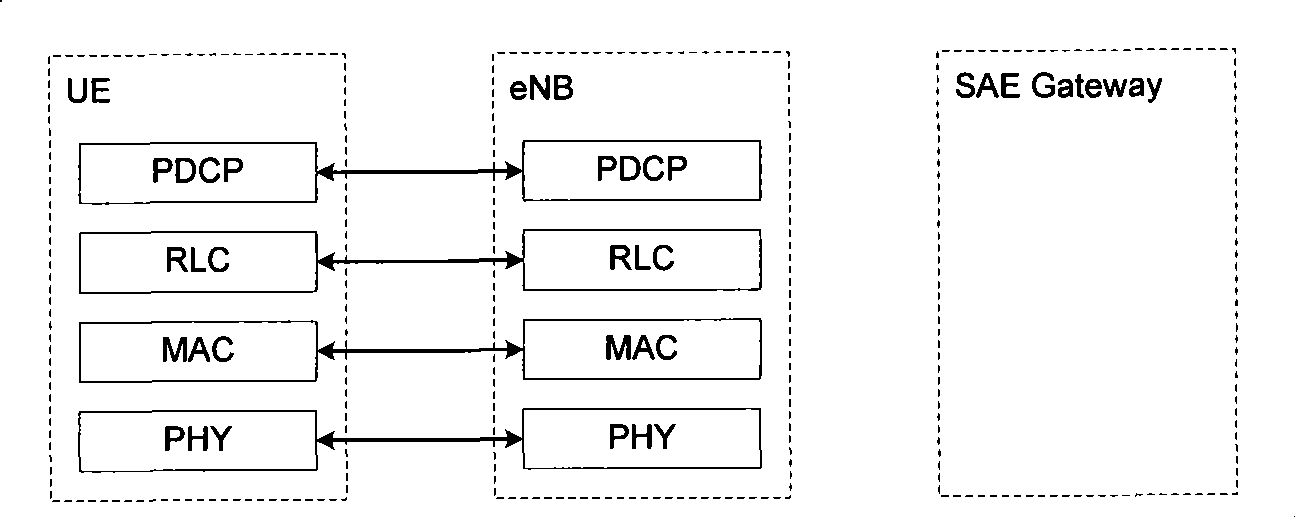
figure 1 Among them, the UE side is configured with an RLC entity, and the eNB side is also configured with an RLC entity. If the data service needs to transmit data in the RLC confirmation mode, once data congestion occurs and there is no better flow control mechanism to control data transmission, then Will cause data loss, which will affect the performance of the E-UTRAN system, and even the communication link will be interrupted

Method used


Image

  • Flow control method, sending entity and receiving entity
  • Flow control method, sending entity and receiving entity
  • Flow control method, sending entity and receiving entity

Examples


Embodiment 1

[0061] see Figure 5 , Figure 5 It is a flowchart of flow control performed by a receiving entity in Embodiment 1 of the present invention. The process may include the following steps:

[0062] Step 501 , the sending entity on the UE side judges whether the PDU to be sent is allowed to be sent according to the state of the current sending window, and sends the PDU to the receiving entity of the eNB if it is allowed to be sent.

[0063] In practical applications, the physical storage space of the sending window is limited and has an upper limit. Correspondingly, the number of PDUs that can be stored in the sending window is also limited. Therefore, the preset number of allocated PDUs used as markers The serial number has a range. If the field of SN is 10 bits (bits), then the range of SN is 0 to 2 10 -1. If the amount of data buffered in the sending window has not yet reached the upper limit of the physical buffer space, and among the cached PDUs, the maximum serial number...

Embodiment 2

[0096] see Figure 6 , Figure 6 It is a flowchart of flow control performed by the receiving entity in Embodiment 2 of the present invention. The process may include the following steps:


PUM


Abstract

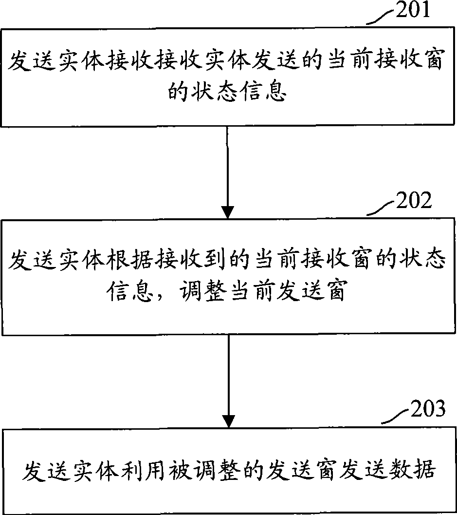
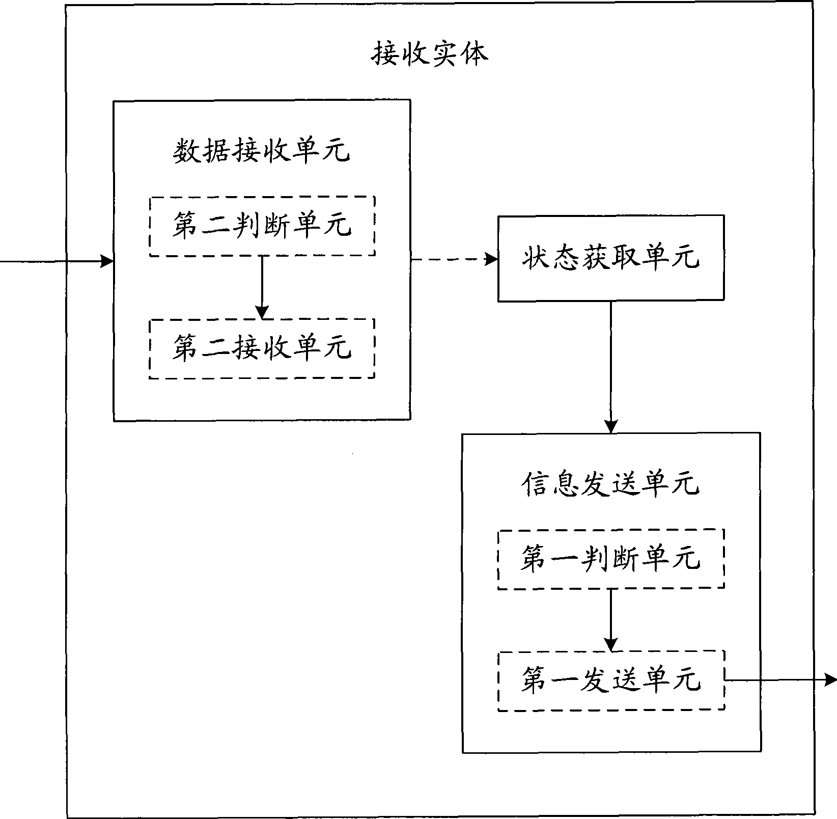
The embodiment of the invention provides a flow control method comprising that: the state information of a present receiving window which is transmitted by a receiving entity is received; a present transmitting window is adjusted according to the state information of the present receiving window; the adjusted transmitting window is used for transmitting data. The embodiment of the invention also provides a receiving entity and a transmitting entity and a plurality of flow control methods. By adopting the technical proposal provided by the embodiment of the invention, the receiving entity directly informs the state information of the present receiving window to the transmitting entity, and the transmitting entity adjusts the present transmitting window according to the state information of the present receiving window; on one hand, the data size which can be scheduled by the receiving entity can be effectively controlled and the effect that the transmitting entity is directly controlled to transmit data by the receiving entity can be realized; on the other hand, as the receiving entity can directly control the transmitting entity to transmit data, the technical proposal which is provided by the embodiment of the invention is suitable for communication systems like E-UTRAN.

Description

technical field [0001] The present invention relates to the technical field of communication, in particular to a flow control method, a sending entity and a receiving entity. Background technique [0002] In the R5 version of the Wideband Code Division Multiple Access (WCDMA) system, when the downlink data is sent through the High Speed ​​Downlink Shared Channel (HS-DSCH, High Speed ​​Downlink Shared Channel), the data to be sent will be sent by the radio network controller ( The radio link control layer (RLC, Radio Link Control) entity of the RNC, Radio Network Controller, is submitted to the upper layer through the interface between the RNC and the base station (NodeB), that is, the high-speed media access control (MAC-hs, Medium Access Control High Speed) entity. When the data needs to be sent by the RLC entity of the RNC in AM (Acknowledgment Mode), in order to try to balance the correctness of data transmission and reduce the data transmission delay, the MAC-hs entity ...

Claims


Application Information

Patent Timeline
IPC IPC(8): H04L12/56H04L1/16H04L12/28H04L47/27
Inventor 邵飞
Owner HUAWEI TECH CO LTD
Why Eureka
Try Eureka