Tread sipe including locking portion

A technology of sipes and tread patterns, which is applied to tire treads/tread patterns, vehicle parts, transportation and packaging, etc., can solve problems such as the reduction of tread pattern rigidity, and achieve the effect of maintaining effectiveness

Active Publication Date: 2011-12-14
OCIETE DE TECH MICHELIN
View PDF0 Cites 0 Cited by
  • Summary
  • Abstract
  • Description
  • Claims
  • Application Information

AI Technical Summary

Problems solved by technology

In contrast, the width of these grooves results in a reduction in the stiffness of the tread pattern when rolling or when subjected to loads tangential to the contact area between the tire and the road surface

Method used


Image

  • Tread sipe including locking portion
  • Tread sipe including locking portion
  • Tread sipe including locking portion

Examples


Embodiment Construction

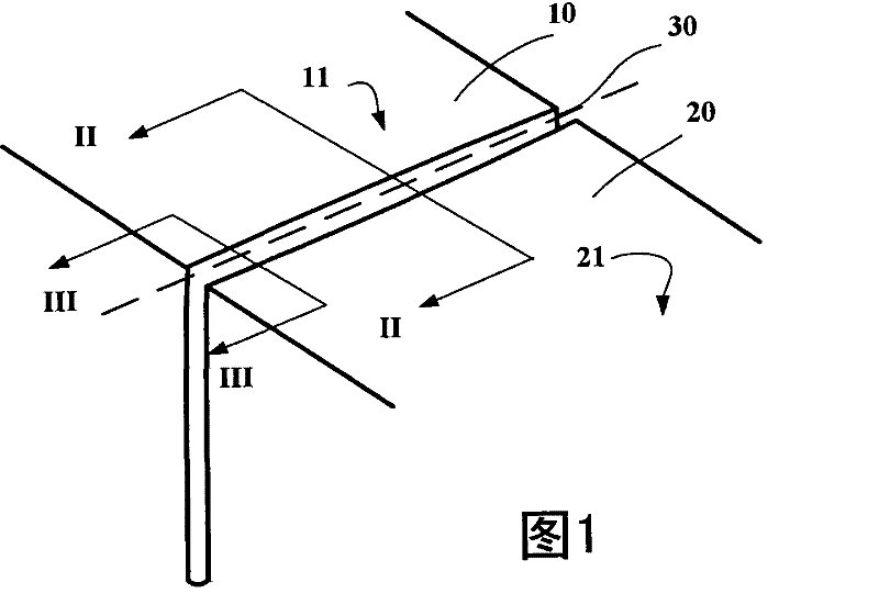
[0023] figure 1 A partial view of a tire tread provided with a sipe according to the invention is shown. exist figure 1 , the two rubber components 10, 20 of the tread pattern are separated from each other by a sipe 30 having an average width greater than 1.0 mm. The two rubber components 10 , 20 of the tread pattern have outer surfaces 11 , 21 which come into contact with the road surface during running, these surfaces 11 , 21 forming part of the tread surface of the tread.

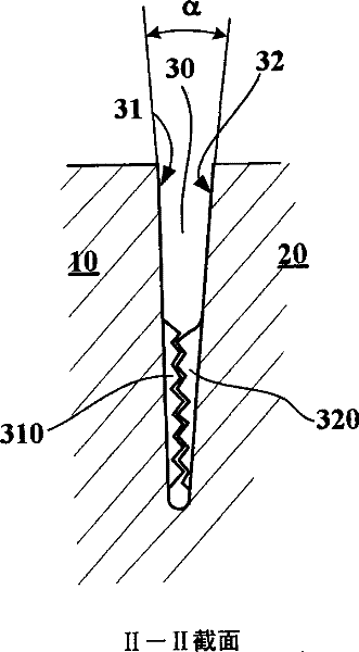
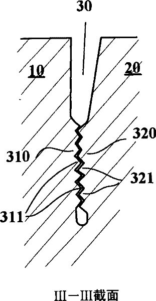
[0024] figure 2 and 3 shows cross-sectional views of the tread taken along section planes II-II and III-III, which are perpendicular to the tread surface and at figure 1 identified in the .

[0025] figure 2 The edges of the main walls 31 , 32 of the sipe 30 in the section plane are shown, said walls 31 , 32 forming an angle α of 5 degrees therebetween. The virtual intersection of these edges is in the thickness of the tread. In an alternative form of the illustrated embodiment, the width of th...


PUM


Abstract

A tire tread comprising a plurality of sipes (30), each sipe being delimited by two opposing main walls (31, 32), each of the said walls consisting of a mean surface of which the intersection with the tread surface in the initial condition forms an edge, the mean width of each sipe measured as the mean distance between the edges formed by the opposing main walls (31, 32) of the said sipe on the tread surface in the initial condition is at least equal to 1.5 mm, each of the main walls (31, 32) comprising at least one locking region (310, 320), each locking region collaborating with a locking region opposite in such a way as to mechanically block relative movements of the said walls at least when the tire is in contact with the road surface.

Description

technical field [0001] The present invention relates to a new shape of the sipe formed in the tread and a molding for molding this type of sipe in the elastic material used for the tread. Background technique [0002] In order to increase the grip of tires mounted on passenger vehicles, especially on roads covered with snow and / or black ice, it is known to place bezels on the tread of the tire (ie the part of the tire that comes into contact with the ground during driving). The cuts generally referred to in the invention are obtained by embossing during the molding and curing operations of the tyre, or alternatively, after said tire has been cured. Among the cuts are sipes, ie spaces separating the two surfaces of the elastomeric material, these spaces typically being less than 3.0 millimeters (mm) in width in the case of passenger vehicle or heavy goods vehicle tires. The width can drop down to zero, that is to say the almost constant contact of the opposing surfaces defin...

Claims


Application Information

Patent Timeline
Patent Type & Authority Patents(China)
IPC IPC(8): B60C11/12
CPCB60C11/12B60C11/1218B60C11/1281B60C11/125
Inventor R·苏米
Owner OCIETE DE TECH MICHELIN
Why Eureka
Try Eureka