
Piezoelectric triggering mechanism

A triggering device, piezoelectric technology, used in transportation and packaging, tire measurement, vehicle components, etc., can solve problems such as damage to the function of piezoelectric equipment, obstruction, etc., to achieve the effect of a reliable signaling method

Active Publication Date: 2009-04-01
MICHELIN & CO (CIE GEN DES ESTAB MICHELIN)
View PDF3 Cites 1 Cited by
  • Summary
  • Abstract
  • Description
  • Claims
  • Application Information

AI Technical Summary

Problems solved by technology

Such an event would interfere with or damage the intrinsic function of the piezoelectric device and require replacement of the piezoelectric component

Method used


Image

  • Piezoelectric triggering mechanism
  • Piezoelectric triggering mechanism
  • Piezoelectric triggering mechanism

Examples


Embodiment Construction

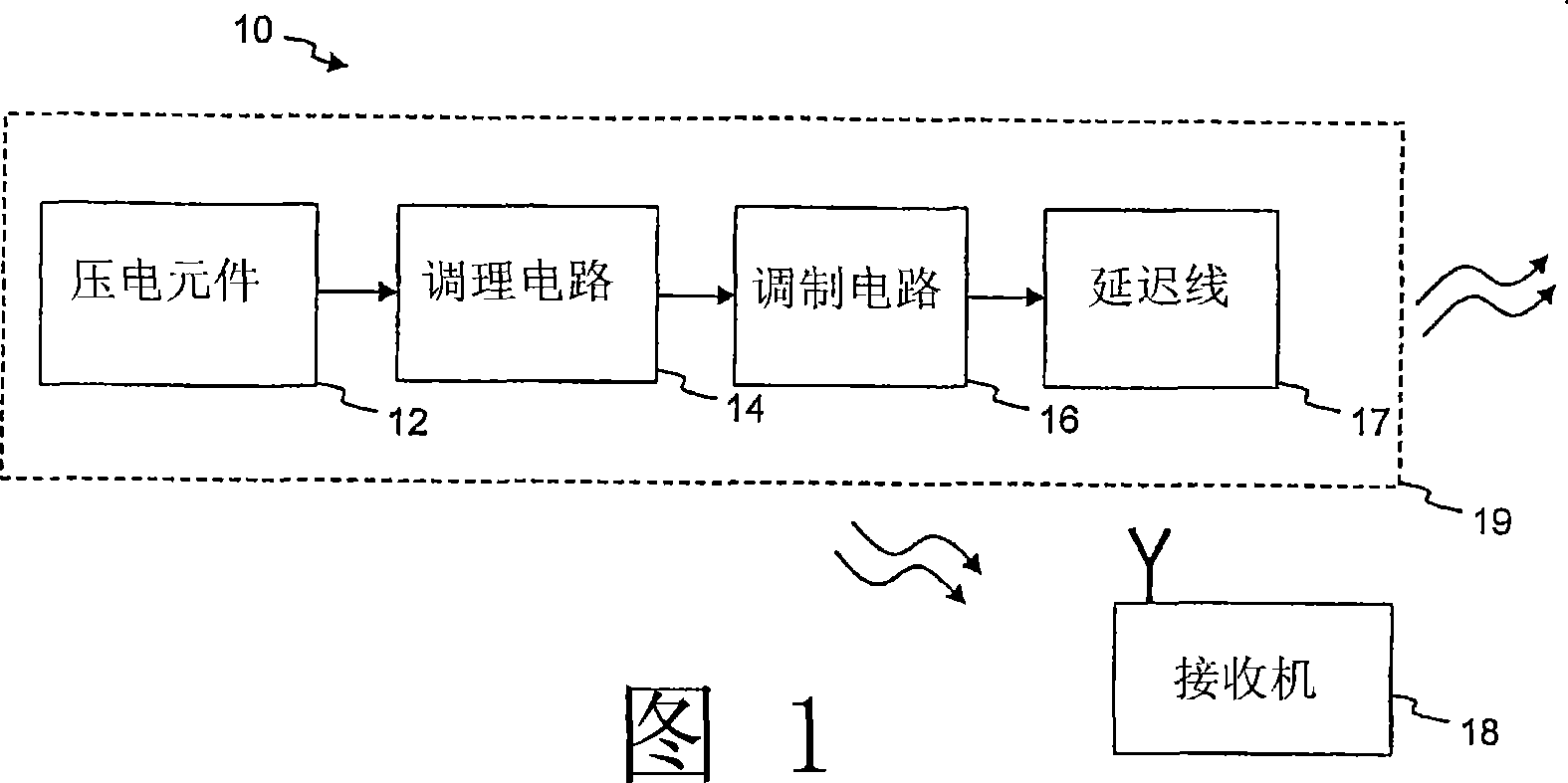
[0026] The presently disclosed subject matter relates to a piezoelectric device and associated circuit elements that collectively function as a self-powered triggering device upon the occurrence of certain events, such as those indicated by a number of mechanical forces used to rupture or break piezoelectric devices, A relatively large energy pulse signal (ie, a burst of electromagnetic energy) is thereby generated. More specific aspects of the piezoelectric trigger device include the schematic hardware components that can be used for the device, which are described below in conjunction with FIG. 1 .

[0027] Referring to FIG. 1 , a piezoelectric trigger device 10 includes a piezoelectric element 12 configured to rupture or snap off when subjected to a sufficient amount of mechanical force. The location and configuration of the piezoelectric element 12 is such that the amount of mechanical force indicative of a certain condition (eg, tire rupture or loss of pressure) can cause...


PUM


Abstract

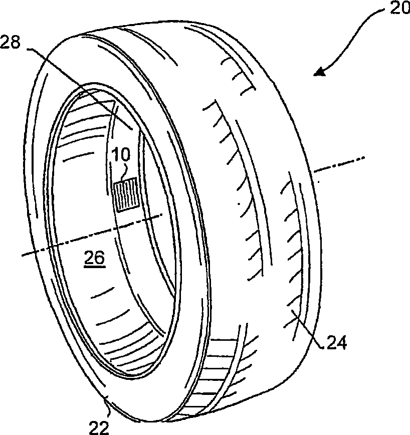
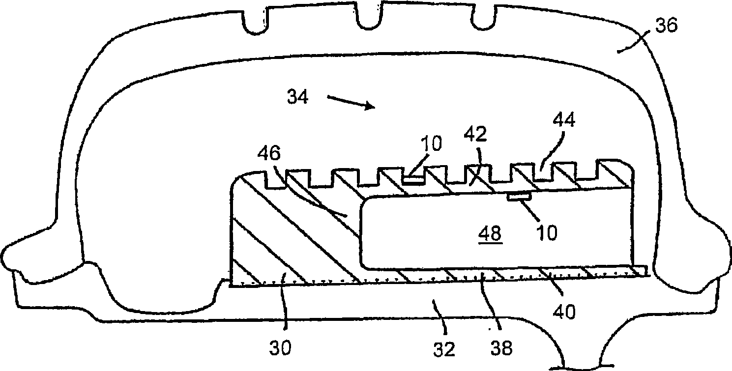
A piezoelectric triggering mechanism (10) includes a piezoelectric element (12), such as the transducer of a SAW device, that is configured to crack or break upon being subjected to excessive levels of mechanical force or other triggering mechanisms, thus generating a burst of electromagnetic energy. The large impulse of energy can then be conditioned (14) through resonant circuits or antennas and modulated (16) with an identification pattern through appropriate structures (such as SAW electrodes) to send a breakage indication signal to a remote receiver (18). Piezoelectric elements (12) may be integrated with a pneumatic tire structure to provide indication upon pressure loss or tire failure. Piezoelectric elements (12) may also be integrated with safety support features of some tire structures to provide indication of tire operation in a run-flat mode of operation. Related aspects of the present piezoelectric triggering technology employ a piezoelectric element (12) in a trigger detection method, which may involve detection of such occurrences as breach of security via opening of a sealed access structure or breakage of a glass panel, deployment of an airbag, loss of pressure or excess deflection in a tire, presence of smoke in a given location, and other rupture and sensor applications.

Description

technical field [0001] The present invention relates generally to a piezoelectric device and its associated components for use as a self-powered trigger device for detecting the occurrence of an event. Piezoelectric elements can be configured to snap off in response to certain events, producing a relatively large energy pulse signal that can be conditioned and stored for later detection or relayed immediately to a remote location. Background technique [0002] The combination of electronics and pneumatic tire construction brings many practical benefits. Tire electronics may include sensors and other components to obtain information about various physical parameters of the tire, such as temperature, pressure, tire revolutions, vehicle speed, etc. This performance information is useful in tire monitoring and warning systems, and may even be used with feedback systems to adjust appropriate tire pressure levels and employed with vehicle performance and control systems. [0003...

Claims


Application Information

Patent Timeline
Patent Type & Authority Applications(China)
IPC IPC(8): B60C23/02B60C23/00
CPCB60C23/0411B60C23/0493
Inventor J·C·辛尼特J·D·阿达姆松G·P·奥布赖恩
Owner MICHELIN & CO (CIE GEN DES ESTAB MICHELIN)
Learn More