

Medicament filling system
a filling system and medicament technology, applied in the field of medicament filling system, can solve problems such as inconvenience and inefficiency, and achieve the effects of preventing medicament backflow, efficient and improved accuracy of medicament, and preventing medicament backflow
- Summary
- Abstract
- Description
- Claims
- Application Information
AI Technical Summary
Benefits of technology
Problems solved by technology
Method used
Image

Examples
second embodiment
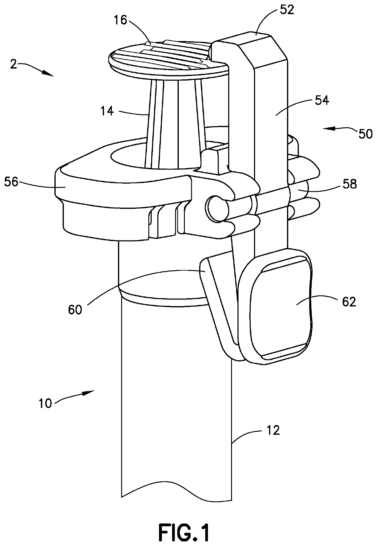
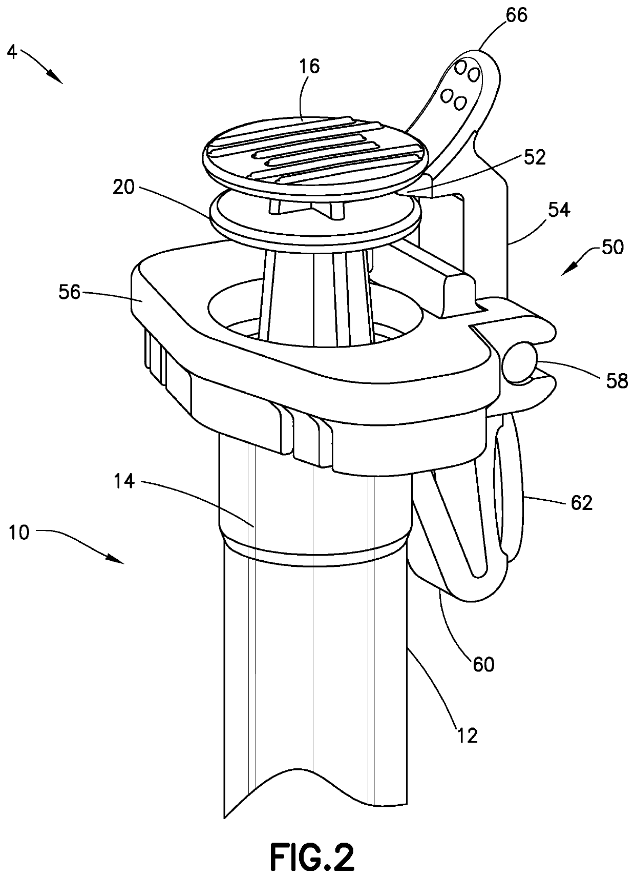
[0035]FIG. 2 illustrates a syringe assembly 4 according to a This embodiment discloses the syringe 10 and the locking assembly 50 as similarly described above with the following modifications. The plunger head 16 of the syringe 10 includes a plunger head platform 20. The platform 20 is disposed below the plunger head 16 such that a gap is present between the two features. The platform 20 is preferably molded as part of the plunger 14 but alternately can be a separate part attached to the plunger 14. The hook 52 of the locking assembly 50 is advantageously configured to engage the gap to lock the plunger 14 after the medicament is dispensed from the barrel 12 of the syringe 10.
[0036]Additionally, the hook 52 includes a plurality of protrusions 66 that provide a depressible surface. Accordingly, the user can advantageously apply a force to the hook 52 where the plurality of protrusions 66 are located or apply a force to the button 62 to move the hook 52 from an engaged, locked positi...
third embodiment
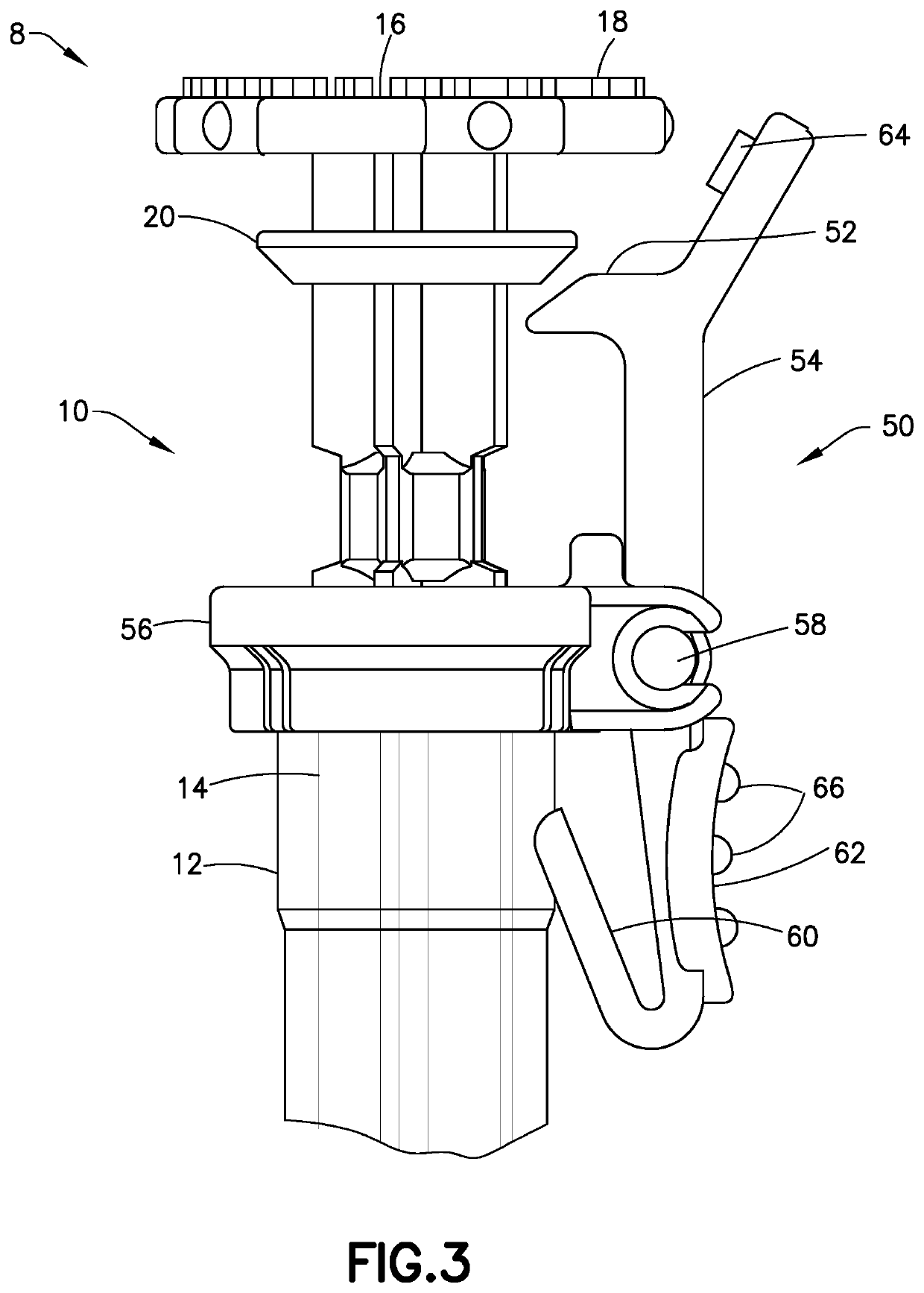
[0037]FIGS. 3-5 illustrate a syringe assembly 6 according to a This embodiment discloses the syringe 10 and the locking assembly 50 as similarly described above with the following modifications. The plunger head 16 includes a dial dose 18. The dial dose 18 indicates a dosage unit amount. Specifically, the plunger head 16 is rotated to set a desired dose identified by the dial dose 18.
[0038]In addition, the locking assembly 50 includes a position indicator 64 shaped as an arrowhead. The position indicator 64 advantageously cooperates with the dial dose 18 to identify a dose position of the plunger head 16. As illustrated in FIG. 5, the position indicator 64 points to a specific dosage amount expressed by the dial dose 18 that is set by the user via rotation of the plunger head 16. The button 62 on the locking assembly 50 also includes protrusions 66 that provide a friction surface for the user to depress the button 62.
[0039]In operation, FIGS. 3 and 4 illustrate an unlocked position...
fourth embodiment
[0040]FIGS. 6 and 7 illustrate a syringe assembly 8 according to a This embodiment discloses the syringe 10 as similarly described above with the following modifications. This embodiment incorporates a dose selector 70 with the syringe 10 to advantageously provide haptic feedback to the user when setting a dose.
[0041]The plunger 14 of the syringe 10 is modified to cooperate with the dose selector 70. Specifically, the plunger 14 includes a plurality of axial ribs 24 extending along a length of the plunger 14. The axial ribs 24 provide stability and stiffness to the plunger 14. A curved indent 28 is disposed between each of the adjacent axial ribs 24.
[0042]FIG. 6 illustrates that a vertical portion of the plurality of axial ribs 24 includes a notch 26. A cross section of the plunger 14 at the notch 26 is illustrated in FIG. 7. The notch 26 advantageously provides a smooth raised surface around the plunger 14. The notch 26 also advantageously provides a continuous surface between the...
PUM
 Abstract
Description
Claims
Application Information